Methods and systems for aircraft systems health trend monitoring

a technology for aircraft systems and subsystems, applied in the field of aircraft, can solve problems such as difficult detection of subsystems or components, system or component abnormal operation, and monitoring methods that are not designed to detect subtle performance degradation

Active Publication Date: 2016-01-12
GULFSTREAM AEROSPACE CORP
View PDF9 Cites 33 Cited by
  • Summary
  • Abstract
  • Description
  • Claims
  • Application Information

AI Technical Summary

Benefits of technology

[0004]In one embodiment, an aircraft includes a plurality of sub-systems a health and trend monitoring system associated with one or more of the plurality of sub-systems. The health and trend monitoring system includes a plurality of sensors each providing sensor signal and a reference signal generator providing a reference signal from a subset of the sensor signals. The system also includes a comparator associated with each sensor for comparing a respective sensor signal to the reference signal to provide difference signal associated with the respective sensor providing the sensor signal. A monitor associated with each sensor compares the difference signal to a threshold value and generates a maintenance message for the respective sensor when the difference signal exceeding the threshold value.

Problems solved by technology

However, due to the need to preserve system availability during operations, these fault monitoring methods are generally not designed to detect subtle performance degradation of a sensor.
When an aircraft is in flight, it can be difficult to detect when sub-systems or components of an aircraft begin to operate abnormally, and / or to correctly diagnose the specific source that is causing that sub-system or component to operate abnormally.
These abnormal operating conditions may persist after the aircraft has landed in some cases, but not all cases, which can make it more difficult to correctly diagnose the specific source that is causing that sub-system or component to operate abnormally.

Method used


Image

  • Methods and systems for aircraft systems health trend monitoring
  • Methods and systems for aircraft systems health trend monitoring
  • Methods and systems for aircraft systems health trend monitoring

Examples


Embodiment Construction

[0015]As used herein, the word “exemplary” means “serving as an example, instance, or illustration.” The following detailed description is merely exemplary in nature and is not intended to limit the invention or the application and uses of the invention. Any embodiment described herein as “exemplary” is not necessarily to be construed as preferred or advantageous over other embodiments. All of the embodiments described in this Detailed Description are exemplary embodiments provided to enable persons skilled in the art to make or use the invention and not to limit the scope of the invention, which is defined by the claims. Furthermore, there is no intention to be bound by any theory presented in the preceding background or the following detailed description.

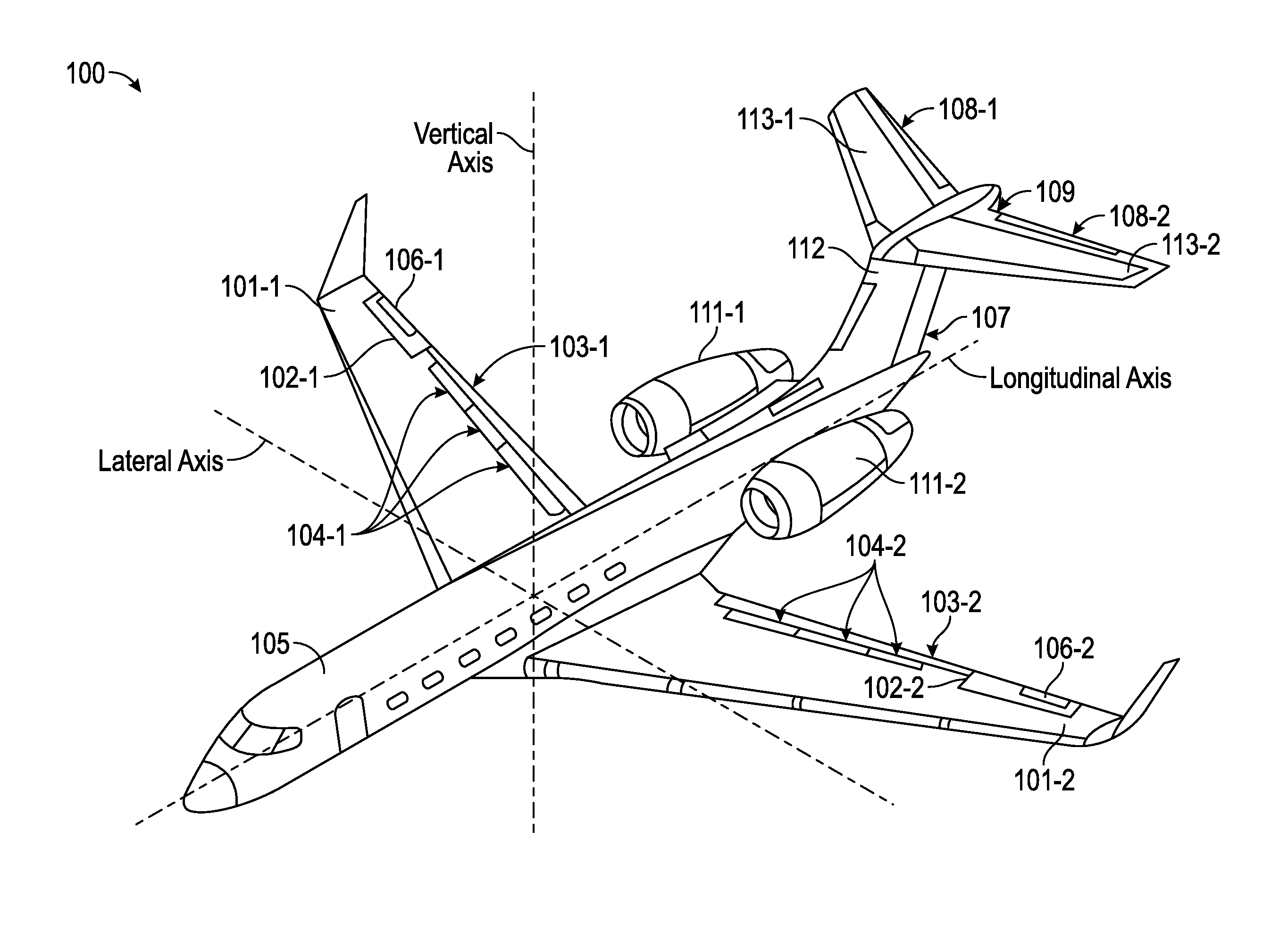
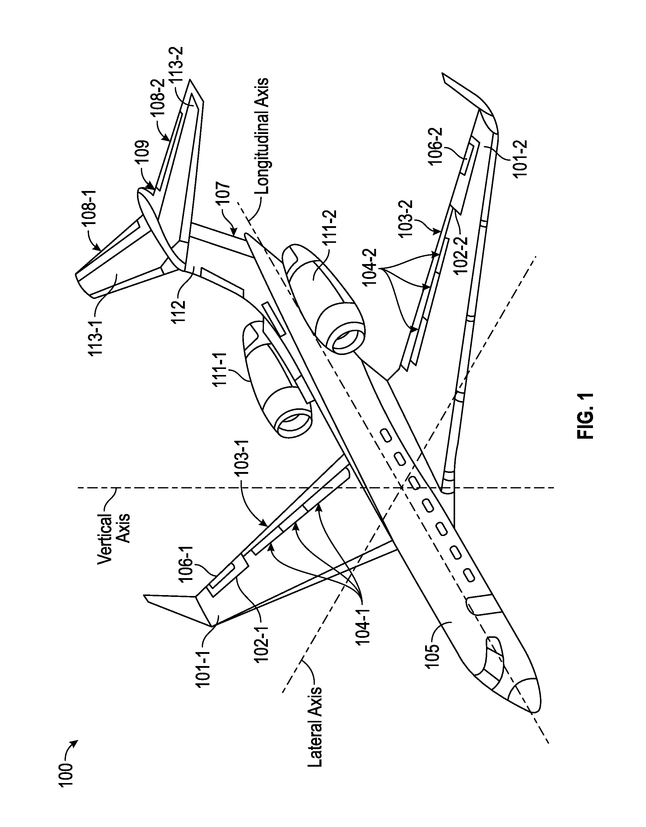
[0016]FIG. 1 is a perspective view of an aircraft 100 that can be used in accordance with the exemplary disclosed embodiments. In accordance with one non-limiting implementation, the aircraft 100 includes a fuselage 105, two main ...


PUM


Abstract

In one embodiment, a method for health and trend monitoring for aircraft systems includes receiving, by a processor on the aircraft, a plurality of sensor signals from a respective plurality of sensors onboard the aircraft and determining a reference signal from a subset of the plurality of sensor signals. Next, each of the plurality of sensor signals is individually compared to the reference signal to provide a plurality of difference signals. Each of the plurality of difference signals is compared to a threshold value, and a maintenance message is provided for any respective sensor associated with any of the plurality of difference signals exceeding the threshold value. An aircraft employing the health and trend monitoring system is also disclosed.

Description

TECHNICAL FIELD[0001]Embodiments of the present invention generally relate to aircraft, and more particularly relate to methods and systems for monitoring systems and subsystems on an aircraft.BACKGROUND[0002]Modern aircraft are often equipped with sophisticated systems that report information and store in-flight data. For safety critical subsystems, conventional aircraft typically include a fault monitoring method configured to reject failed sensor inputs. However, due to the need to preserve system availability during operations, these fault monitoring methods are generally not designed to detect subtle performance degradation of a sensor. When an aircraft is in flight, it can be difficult to detect when sub-systems or components of an aircraft begin to operate abnormally, and / or to correctly diagnose the specific source that is causing that sub-system or component to operate abnormally. These abnormal operating conditions may persist after the aircraft has landed in some cases, b...

Claims


Application Information

Patent Timeline
Patent Type & Authority Patents(United States)
IPC IPC(8): G07C5/00G07C5/08B64D45/00
CPCB64D45/00G07C5/0808G07C5/0841B64D2045/0085G05B23/0235G05B2219/14016G05B2219/14126G05B2219/37325G05B2219/42318G05B2219/45071
Inventor CHEN, JEFF
Owner GULFSTREAM AEROSPACE CORP
Why Eureka
Try Eureka