Run-through switch rods

a switch rod and switch rod technology, applied in the direction of scotch-block locking mechanism, mechanical device of scotch-block, railway signalling, etc., can solve the problems of train derailment and difficult switch conditions

Inactive Publication Date: 2016-01-19
NORFOLK SOUTHERN
View PDF22 Cites 7 Cited by
  • Summary
  • Abstract
  • Description
  • Claims
  • Application Information

AI Technical Summary

Problems solved by technology

These post-run-through switch conditions may be problematic if a train somehow moves in reverse through the switch.
For example, if the switch is damaged and remains in an “in-between” position as shown in FIG. 2B (or otherwise not securely closed or locked in the run-through position), the train wheels moving in reverse (i.e., in facing-point direction) will not be properly guided by the switch, which could cause derailment of the train.
Even if the switch has returned to its pre-run-through position as shown in FIG. 2A, the reversing train could travel too fast for the switched curve to the secondary tracks, again potentially causing derailment.

Method used


Image

  • Run-through switch rods
  • Run-through switch rods
  • Run-through switch rods

Examples


Embodiment Construction

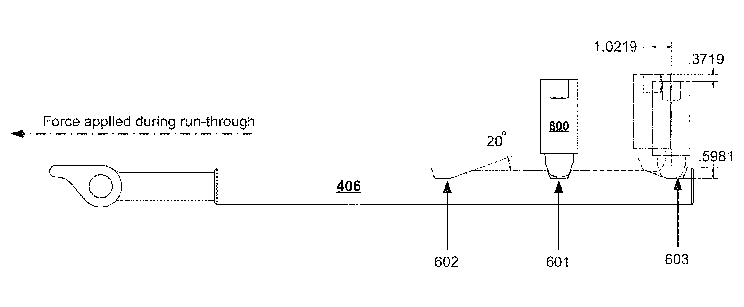
[0026]Embodiments of the present invention provide for innovative designs and use of switch rods to prevent derailment of a train that traverses through a previously trailed railroad switch. In light of uncertain, and sometimes dangerous, conditions of the railroad switch after it has been run through by a trailing train, the inventor finds it desirable to have a switch that securely maintains or locks the switch points in the position forced by the run-through, rather than reverting to the position set before the run-through (or to any other position). A mechanism is therefore provided in the switch rod to accommodate a run-through and thereafter automatically cause the switch to remain in the same condition forced by the run-through. As a result of the design and use of the inventive switch rod assembly, the non-ideal conditions of the post-run-through railroad switch can be avoided, thereby eliminating or reducing the risk of derailment when a train attempts to traverse through a...


PUM


Abstract

Embodiments of innovative designs and use of switch rods are disclosed. In one particular embodiment, a method of preventing derailment of a train traveling through a previously run-through railroad switch may include installing a railroad switch rod assembly to couple a switch point of a railroad switch with a railroad switch stand. The method may also include configuring a locking mechanism in the railroad switch rod assembly such that, upon a railway vehicle trailing the railroad switch in a first direction, the locking mechanism maintains the railroad switch in a condition that accommodates safe movement of the railway vehicle through the railroad switch in a second direction opposite to the first direction.

Description

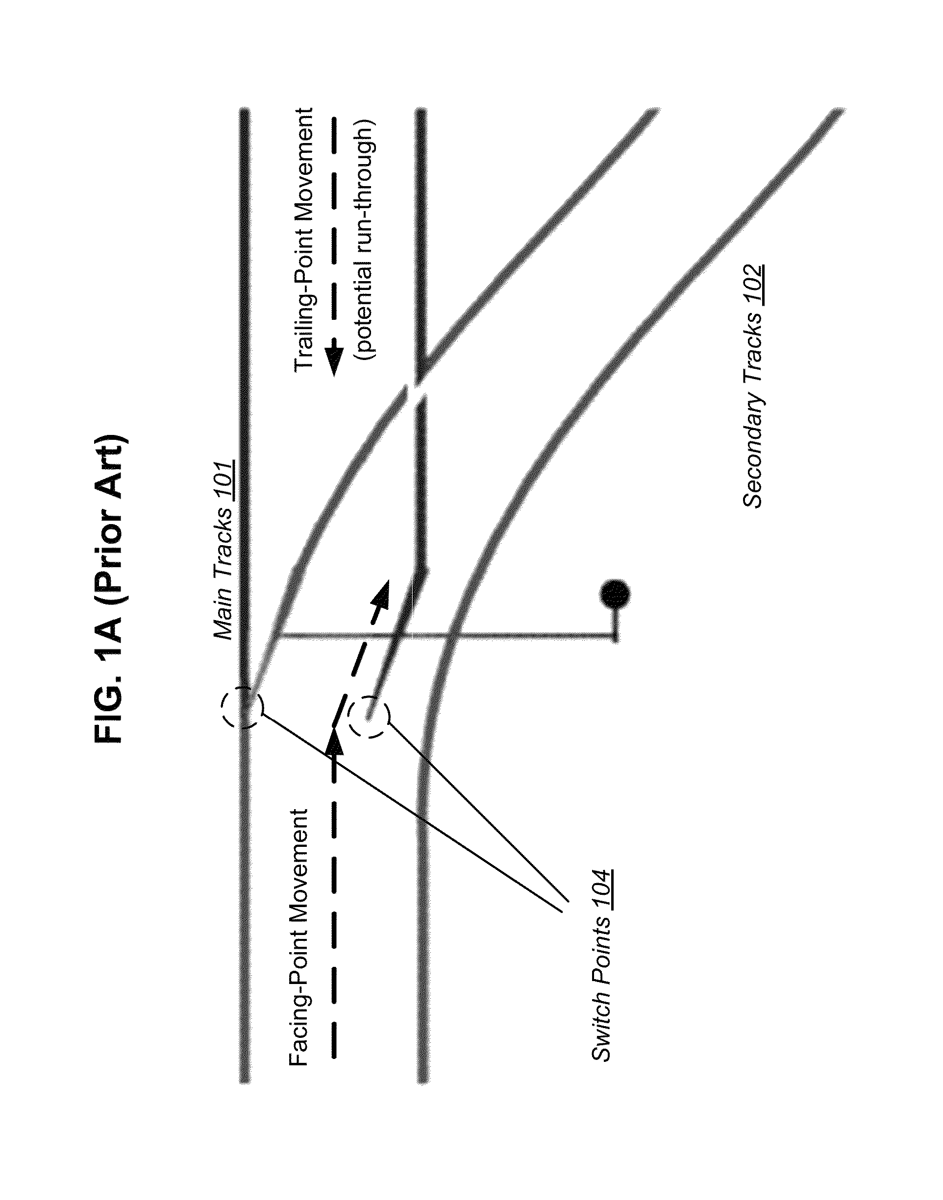
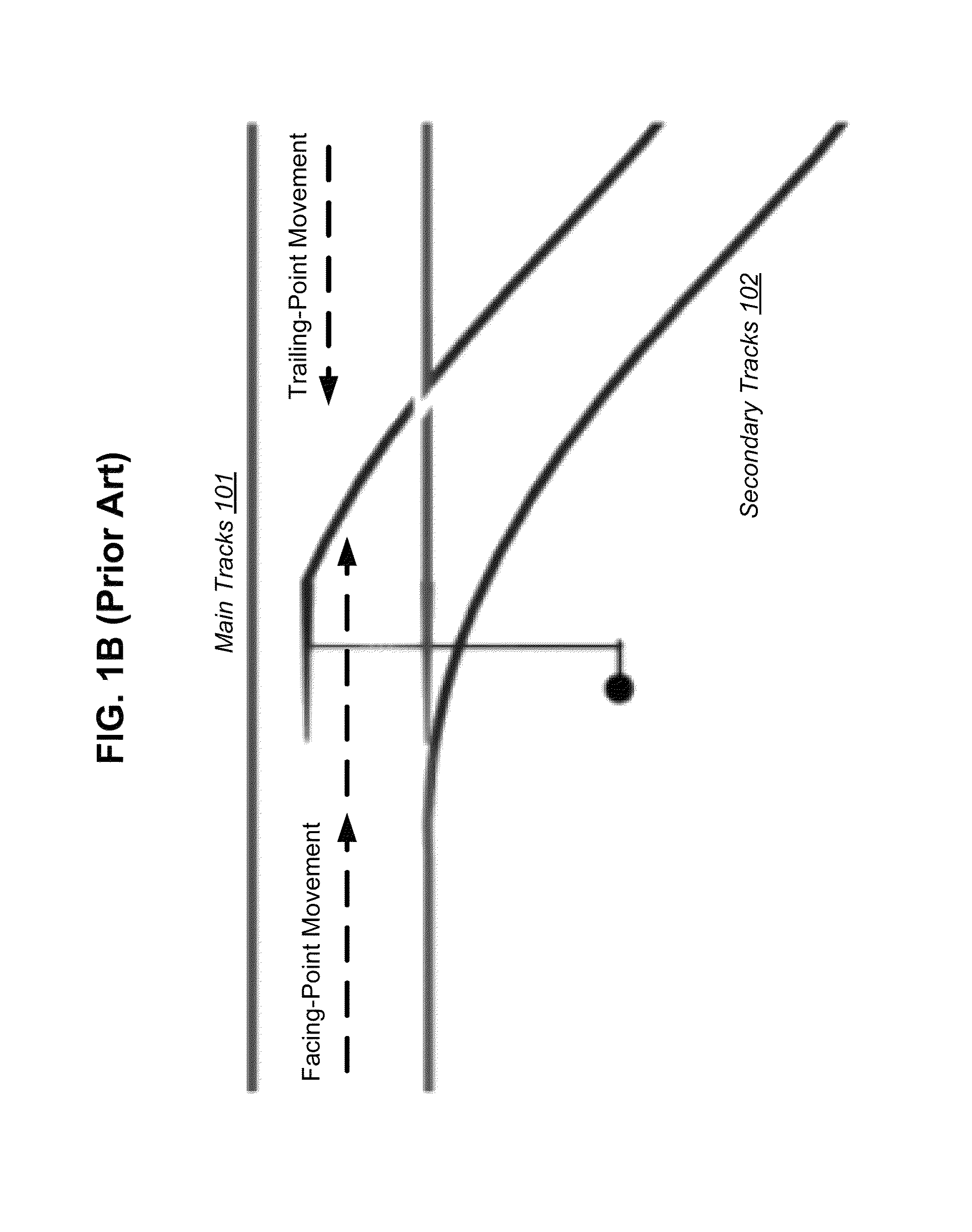
FIELD OF THE INVENTION[0001]The present invention relates generally to railway equipment. More particularly, the present invention relates to innovative designs and use of switch rods to prevent derailment of a train that reverses through a previously trailed railroad switch.BACKGROUND OF THE INVENTION[0002]A railroad switch is a well-known mechanical installation that enables railway trains to be guided from one set of tracks to another set of tracks.[0003]FIGS. 1A-1B show a typical railroad switch located at the intersection of main tracks 101 and secondary tracks 102. The railroad switch has switch points 104 which are mechanically linked so that they move together when toggled from one position to another. As a train approaches the railroad switch along the main tracks 101 and in the facing-point direction, the train wheels are guided along the route determined by which of the two switch points 104 is connected to the track facing the switch. If the left point is connected, as s...

Claims


Application Information

Patent Timeline
Patent Type & Authority Patents(United States)
IPC IPC(8): B61L5/10B61L5/02
CPCB61L5/02B61L5/10
Inventor CARPENTER, BRUCE, A
Owner NORFOLK SOUTHERN
Why Eureka
Try Eureka