Control device for hybrid vehicle

a control device and hybrid technology, applied in the direction of electric propulsion mounting, electric control, machines/engines, etc., can solve the problems of generating gear rattle noise, and achieve the effect of suppressing gear rattle noise, small torque output, and greater change during all-cylinder operation

Active Publication Date: 2016-01-26
TOYOTA JIDOSHA KK
View PDF20 Cites 0 Cited by
  • Summary
  • Abstract
  • Description
  • Claims
  • Application Information

AI Technical Summary

Benefits of technology

[0008]The ranges of torque of the second electric motor at which gear rattle noise is generated differ for different levels of engine torque fluctuation. Due to this, if the range of torque of the second electric motor at which gear rattle noise is generated is set to match high torque fluctuation operation in which torque fluctuation is high, and the operating point of the engine is changed when the torque of the second electric motor enters into this range, then it is possible to suppress gear rattle noise both during high torque fluctuation operation and during low torque fluctuation operation. However, the operating point of the engine is also changed during low torque fluctuation operation in which torque fluctuation is low, even though in this region the torque of the second electric motor does not generate gear rattle noise. Accordingly the fuel consumption is deteriorated, since during low torque fluctuation operation the operating point of the engine is unnecessarily changed. Conversely, if the range of torque of the second electric motor at which gear rattle noise is generated is set to match low torque fluctuation operation in which the fluctuation of torque is low, and the operating point of the engine is changed when the torque of the second electric motor enters within this range, then it is possible to suppress deterioration of the fuel consumption, since the chance of the operating point of the engine being changed during low torque fluctuation operation is reduced. However, since in some cases it is not possible to suppress the generation of gear rattle noise during high torque fluctuation operation, accordingly there is a fear that, in this type of situation, the driver may experience a sense of discomfort. But, with the control device of the present invention, the predetermined range of torque of the second electric motor, which is the condition for the operating point of the engine to be changed, is set to be higher during high torque fluctuation operation, as compared to during low torque fluctuation operation. Accordingly, the operating point of the engine is changed in conditions that are matched both to high torque fluctuation operation and to low torque fluctuation operation. Due to this, it is possible for suppression of gear rattle noise and prevention of deterioration of the fuel consumption to be mutually compatible. It should be understood that low torque fluctuation operation means a type of operation in which the fluctuations of torque are relatively lower than during high torque fluctuation operation.
[0012]During partial cylinder operation, since some of the cylinders are deactivated, accordingly the torque that can be outputted is small as compared to all-cylinder operation. To put it in another manner, the normal line that connects the normal operating points during partial cylinder operation is positioned more towards the low torque side than the normal line during all-cylinder operation. If the operating point of the engine is changed by changing over the differential mechanism to the non-differential state, then the operating point of the engine changes towards the high rotational speed low torque side. When the amount of change when the operating point is changed by changing over the differential mechanism to the non-differential state during all-cylinder operation, and the amount of change when the operating point is changed by changing over the differential mechanism to the non-differential state during partial cylinder operation are compared together in the same vehicle speed condition, the amount of change during all-cylinder operation is greater as compared to the amount of change during partial cylinder operation. For each of all-cylinder operation and partial cylinder operation, it is normal for the normal line to be set in consideration of attaining as good a fuel consumption as possible. Accordingly, if the operating point of the engine that is positioned upon the normal line is changed, it is desirable for this amount of change to be as small as possible. Due to this, when the operating point of the engine is to be changed during partial cylinder operation, it is appropriate to implement this by changing over the differential mechanism to the non-differential state. On the other hand, when the operating point of the engine is to be changed during all-cylinder operation, changing the operating point of the engine by changing over the differential mechanism to the non-differential state is avoided, and it is more appropriate to change the operating point of the engine while keeping the differential mechanism in its differential state. In the aspect of the present invention described above, the operating point of the engine is changed during all-cylinder operation with the differential mechanism in its differential state, while during partial cylinder operation the operating point of the engine is changed by changing over the differential mechanism to its non-differential state. Since in this manner the operating point of the engine is changed over by an appropriate method, both during all-cylinder operation and during partial cylinder operation, accordingly it is possible to suppress gear rattle noise, while still there is no tendency for the fuel consumption to be deteriorated.

Problems solved by technology

As a result, gear rattle noise is generated due to rotational fluctuations of the engine being transmitted to the output unit, since the output unit and the gear collide together because of mutual backlash.

Method used


Image

  • Control device for hybrid vehicle
  • Control device for hybrid vehicle
  • Control device for hybrid vehicle

Examples


embodiment # 1

Embodiment #1

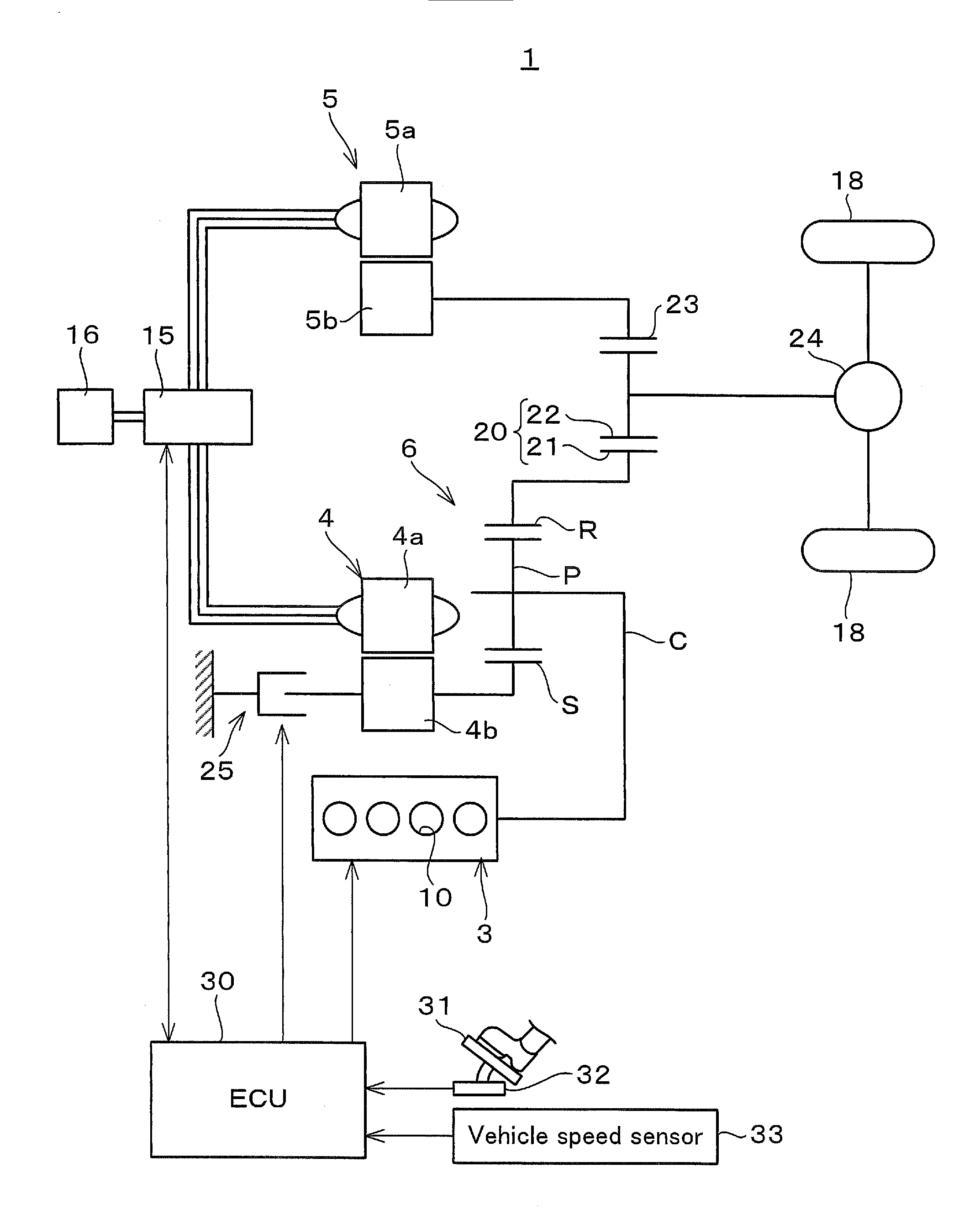
[0024]As shown in FIG. 1, a vehicle 1 is built as a hybrid vehicle in which a plurality of power sources are combined. The vehicle 1 comprises an engine 3 and two motor-generators 4 and 5 that serve as power sources for propulsion. The engine 3 is built as an internal combustion engine of the four cylinder in-line type having four cylinders 10. The engine 3 is able to perform all-cylinder operation in which all of the four cylinders 10 operate, and also partial cylinder operation in which two of the four cylinders 10 are deactivated and the remaining two operate.

[0025]The engine 3 and the first motor-generator 4 are linked to a power split mechanism 6 that serves as a differential mechanism. The first motor-generator 4 has a stator 4a and a rotor 4b. The first motor-generator 4 both functions as a generator that receives mechanical power from the engine 3 after distribution by the power split mechanism 6 and generates electricity, and also functions as an electric motor...

embodiment # 2

Embodiment #2

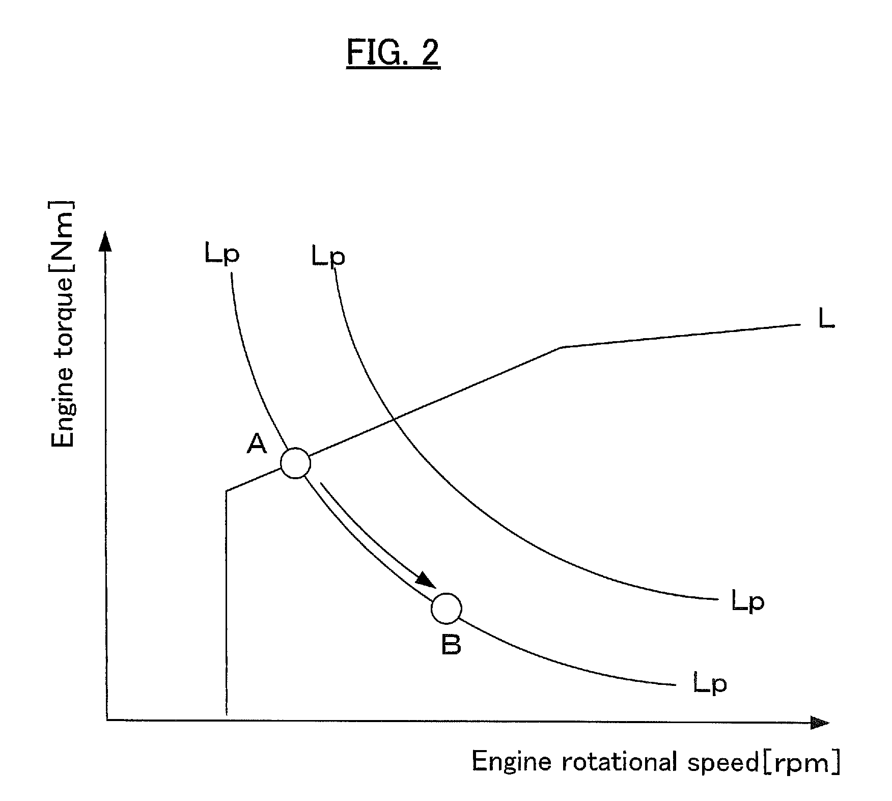
[0036]The second embodiment is distinguished by the feature that change of the operating point of the engine 3 is implemented by operation of the motor locking mechanism 25. In other words, if the motor torque has entered the operating point changeover range R1 or R2, then the ECU 30 operates the motor locking mechanism 25 and prevents rotation of the first motor-generator 4, so that the power split mechanism 6 is changed over from the differential state to the non-differential state. Due to this, none of the torque of the engine 3 is distributed to the first motor-generator 4, and this torque is entirely transmitted to the output gear train 20. In other words, by changing over the power split mechanism 6 from the differential state to the non-differential state, a one-to-one correspondence relationship is established between the rotational speed of the engine 3 and the vehicle speed. Due to this, as shown by the arrow in FIG. 6, the operating point upon the normal line...

embodiment # 3

Embodiment #3

[0038]The third embodiment is distinguished by the feature that the method of changing over the operating point of the engine 3 is changed over between the case of all-cylinder operation and the case of partial cylinder operation. In partial cylinder operation, the torque that can be outputted is smaller as compared with all-cylinder operation, since some of the cylinders are deactivated. In other words, as shown in FIGS. 8A and 8B, the normal line Lb during partial cylinder operation is positioned more towards the low torque side than the normal line La during all-cylinder operation. Since, as described above, the normal lines La and Lb are set so that the fuel consumption of the engine 3 becomes optimum, accordingly the normal lines La and Lb are set so as to pass through the centers of the contour lines Ha and Hb for the thermal efficiency of the engine 3, in other words are set so as to pass through the positions where the thermal efficiency of the engine 3 is at it...


PUM


Abstract

The control device of the present invention causes an engine to perform both partial cylinder operation and also all-cylinder operation, and moreover changes the operating point of the engine when the motor torque of a second motor-generator enters into operating point changeover ranges R1 and R2. The operating point changeover range R2 when the engine is performing partial cylinder operation is set to be wider, as compared to the operating point changeover range R1 when the engine is performing all-cylinder operation.

Description

TECHNICAL FIELD[0001]The present invention relates to a control device applied to a hybrid vehicle that is provided with an engine and an electric motor as power sources for driving.BACKGROUND ART[0002]A hybrid vehicle is per se known in which the power of an engine is divided between a first electric motor and an output unit, and a second electric motor is linked to the output unit via gears. With a hybrid vehicle of this type, the thrust upon the output unit of a gear interposed between the output unit and the second electric motor becomes slack when the torque of the second electric motor becomes near zero Nm. As a result, gear rattle noise is generated due to rotational fluctuations of the engine being transmitted to the output unit, since the output unit and the gear collide together because of mutual backlash. Thus, in order to suppress this type of gear rattle noise, a control device has been proposed (Patent Document #1) with which, when the torque of the second electric mot...

Claims


Application Information

Patent Timeline
Patent Type & Authority Patents(United States)
IPC IPC(8): B60L9/00B60W10/10B60W20/00F02D29/02F02D41/00B60K1/02B60W10/12B60K6/445B60W10/06B60W10/08F02D23/00
CPCB60W20/00B60K6/445B60W10/06B60W10/08B60W10/10B60W10/12F02D29/02F02D41/0087Y02T10/6286Y10S903/902B60W2710/0672B60W2710/083B60W2710/12B60Y2300/435F02D23/00F02D2250/18F02D2250/21Y02T10/6239Y02T10/62
Inventor TAKAHASHI, SATORUMIYAGAWA, TAKESHINAKAJIMA, NORITAKAKAWAMOTO, KOUKISATO, DAIKINAKANO, MASATOSATO, AKIHIROKANAYAMA, TAKESHISUENAGA, SHINICHIRO
Owner TOYOTA JIDOSHA KK
Why Eureka
Try Eureka