Roof vent

a technology for venting devices and roofs, which is applied in the direction of vehicle maintenance, space heating and ventilation details, domestic heating details, etc., can solve the problems of occupant health problems, damage to buildings or structures, and hitting the roofs with sufficient force, and achieves the effect of being convenient to manufacture and install

Active Publication Date: 2016-01-26
CANPLAS INDS
View PDF153 Cites 10 Cited by
  • Summary
  • Abstract
  • Description
  • Claims
  • Application Information

AI Technical Summary

Benefits of technology

[0018]The present invention is directed to a passive roof vent with improvements to help prevent moisture entering from outside of the roof vent to inside of the enclosure, for example moisture condensing on an underside of the cover of a roof vent and dripping into the attic below.
[0019]One embodiment of the present invention has a cover attached to a base, which has an attachment element and an aperture. The attachment element permits the roof vent to be attached to a roof with the aperture in the base positioned over an opening in the roof to permit gases to pass therethrough. The cover is attached to the base and covers the aperture. Preferably the cover includes one or more ribs attached to its underside surface. The one or more ribs are preferably sized and shaped to direct and guide moisture therealong to fall onto the base rather than into the roof opening through the aperture. Preferably the cover also includes a slanted side wall portion extending from a top wall to the base, and the aperture is positioned on the base away from the center of the cover, so that the center of the aperture is displaced from the center of the cover toward the slanted side wall portion. Preferably, the base also includes a pair of moisture deflecting features that are positioned on the base adjacent to the sides of the cover when attached to the base. Each moisture deflecting feature extends along at least a portion of one of the sides of the cover to prevent moisture from flowing, under the influence of gravity, along the base from within an area on the base which is covered by the cover to outside of the covered area.
[0036]wherein said moisture deflecting features prevent moisture flowing under the influence of gravity along said base from within said covered area to outside of said covered area at said nonslope sides.

Problems solved by technology

However, such enclosures do typically require a passive venting device to allow for air flow from the enclosure to the outdoors.
However, in addition to permitting air to flow from the building enclosure to the outside though the roof opening, prior art roof vents also tend to allow moisture to enter the building enclosure from the outside, which can cause damage to the building or structure and fosters growth of mold and mildew which can lead to health problems for occupants.
For example, during periods of heavy rain, the falling rain will hit the roof with sufficient force to bounce under the covers of prior art venting devices, and through their apertures into the enclosures they are venting.
Heavy precipitation can also result in a flow of water along the slope of a roof which splashes and sprays when it encounters a prior art roof vent.
A steeply sloped roof can make this situation worse since water will naturally flow down a steeply sloped roof at a greater velocity as compared to a roof having a moderate slope or no slope at all.
In addition to heavy precipitation, snow and ice melting on a roof may also lead to a flow of water along the slope of the roof.
However, providing a peak on the upstanding portion of the passive vent, or other irregular shapes, creates the potential for other problems, such as for example, over-cutting shingles to match the outline of the roof vent, creating holes for water to gain pathways into the shingles to the roof surface underneath, and into the roof opening bypassing the roof vent altogether.
Providing passive vent devices with other irregular shapes, for example to accommodate attachment parts, especially parts positioned along sides of the venting device, also makes it difficult or inconvenient to install shingles right up against the vent structure.
However, since the collar is positioned forwardly of the sloped apron section, moisture is still liable to work its way through the collar and into the ventilation opening of the Metz roof ventilator.
However, the lack of a separate base makes attaching and sealing the off-ridge roof vent to the roof more difficult.
While attempts have been made by others at directing water about the exterior of venting devices and other devices, none have dealt with the problem of how to prevent moisture condensing on an interior of a passive venting device and dripping into the enclosure.

Method used


Image

  • Roof vent
  • Roof vent
  • Roof vent

Examples


Embodiment Construction

[0066]The present invention is described in more detail with reference to exemplary embodiments thereof as shown in the appended drawings. While the present invention is described below including preferred embodiments, it should be understood that the present invention is not limited thereto. Those of ordinary skill in the art having access to the teachings herein will recognize additional implementations, modifications, and embodiments which are within the scope of the present invention as disclosed and claimed herein. In the figures, like elements are given like reference numbers. For the purposes of clarity, not every component is labelled in every figure, nor is every component of each embodiment of the invention shown where illustration is not necessary to allow those of ordinary skill in the art to understand the invention.

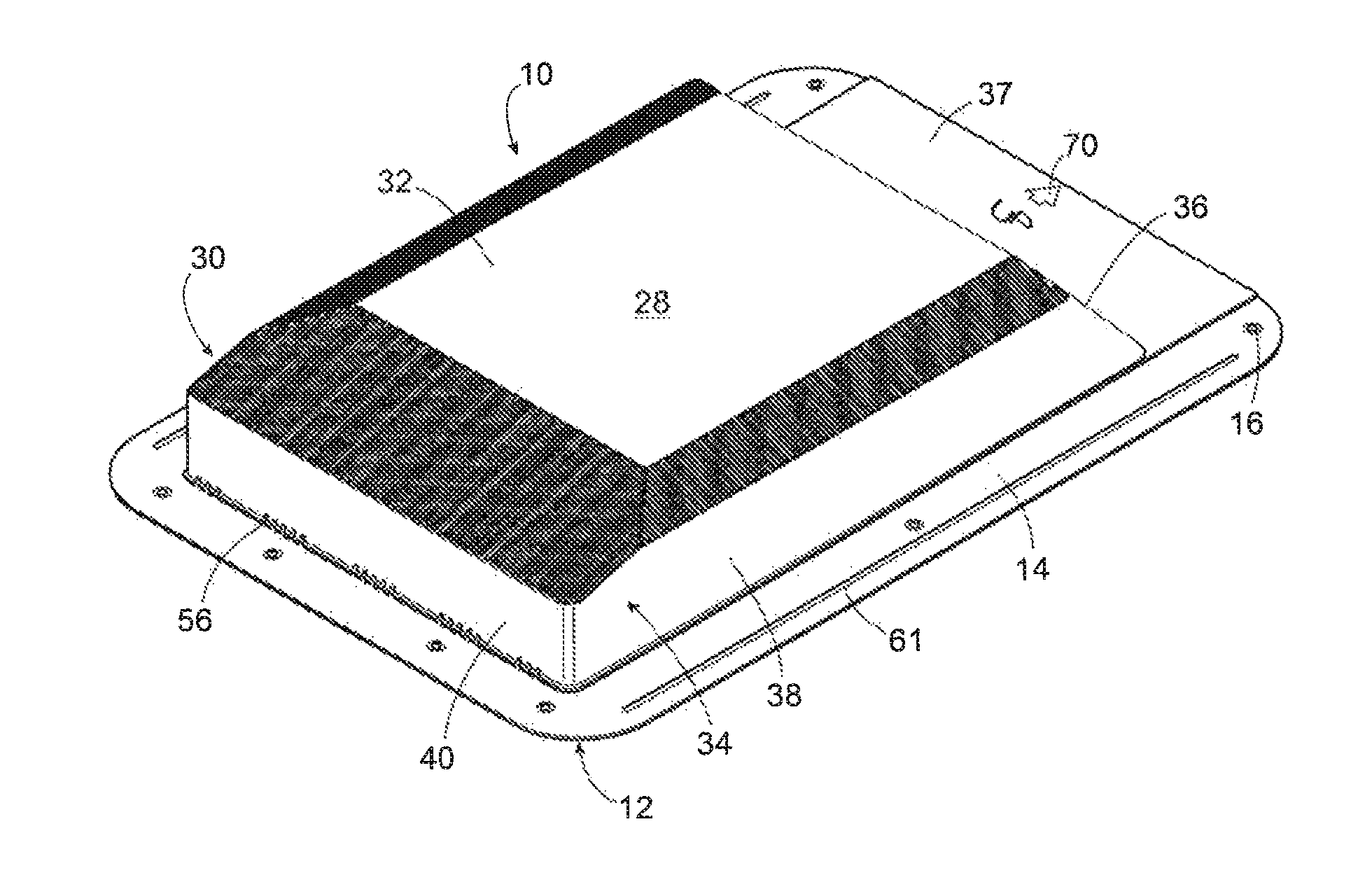
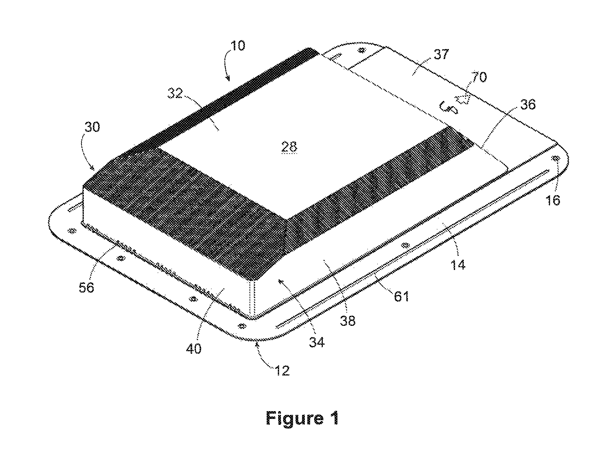
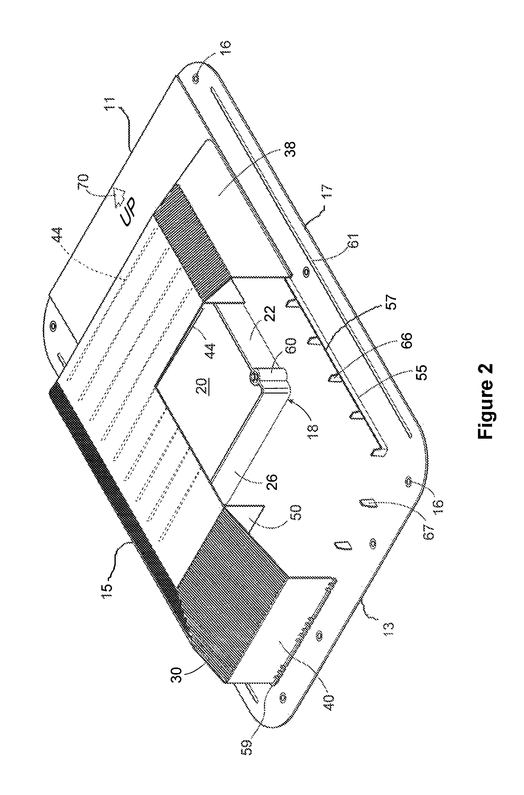
[0067]FIGS. 1 and 2 show a vent 10 according to an embodiment of the present invention, for venting gases and vapours from an enclosure to the outside while...


PUM


Abstract

A vent for a building has a cover attached to a base. The base has an aperture permitting gas to pass. A moisture directing means on an underside of the cover directs moisture move under the influence of gravity to fall outside of the aperture. The cover may include a slanted side wall portion, with the aperture positioned with its center displaced from the center of the cover toward the slanted side. The base may include a pair of moisture deflecting features along at least a portion of one of the nonslope sides to prevent moisture flowing along the base from within an area on the base covered by the cover to outside of the covered area at the nonslope sides. The base may also include a water deflecting ridge on its underside positioned between a downslope edge and the aperture to deflect water away.

Description

CROSS-REFERENCE TO RELATED APPLICATIONS[0001]This application claims priority benefit under 35 U.S.C. §119 of Canadian Patent Application No. 2,753,482, filed 22 Sep. 2011 in the name of Canplas Industries. Ltd., assignee of the present application, and naming as inventors the present inventive entity. The complete disclosure of this priority application is hereby incorporated herein in its entirely by this reference, for all purposes.FIELD OF THE INVENTION[0002]This invention relates generally to the field of venting devices, and in particular to passive venting devices.BACKGROUND OF THE INVENTION[0003]Virtually all buildings and structural enclosures where human activity takes place require venting. The type of venting device employed to provide the required venting will depend on the kind of enclosure to be vented and the use to which the vented space is put. For example, bathrooms containing showers typically have active vents with fans to vent moist air and steam from the enclo...

Claims


Application Information

Patent Timeline
Patent Type & Authority Patents(United States)
IPC IPC(8): F24F13/20B60J7/22E04H12/00B60S1/54B60H1/00F24F13/22F24F7/02
CPCF24F13/222F24F7/02E04D13/178F24F13/20
Inventor MANTYLA, JAMES BRIANBACH, TIMOTHY DUANEBURTCH, DONNA MARIAPROCTOR, KENT DOUGLAS
Owner CANPLAS INDS
Why Eureka
Try Eureka