
Specific location dry yield measurement for forage

a technology for forage and specific locations, applied in baling, agriculture, agricultural tools and machines, etc., can solve the problem of extreme difficulty in determining actual cut yield in meaningful units of measurement with any degree of accuracy, and achieve the effect of optimal baler efficiency

Active Publication Date: 2016-02-09
AGCO CORP
View PDF6 Cites 12 Cited by
  • Summary
  • Abstract
  • Description
  • Claims
  • Application Information

AI Technical Summary

Benefits of technology

The present invention is a method for measuring the cut yield of forage crop materials with precision. Previous methods could only provide relative yield information, but the present invention helps to determine where the yield comes from within the field. This is important for developing better fertilization techniques and other agronomic practices. The invention also addresses the complicating factors of the crop cutting and baling operations by measuring dry yield at specific locations within the field.

Problems solved by technology

However, due to the unique nature of forage crop materials and the many variables that exist in the size, shape and density of the stalks, stems, and mat or stream moving through the machine, it is extremely difficult to determine actual cut yield in meaningful units of measurement with any degree of accuracy.
This gives a total dry yield per unit area, e.g., tons per acre, but does not answer the question of where the yield came from within the field.

Method used


Image

  • Specific location dry yield measurement for forage
  • Specific location dry yield measurement for forage
  • Specific location dry yield measurement for forage

Examples


Embodiment Construction

[0009]The present invention is susceptible of embodiment in many different forms. While the drawings illustrate and the specification describes certain preferred embodiments of the invention, it is to be understood that such disclosure is by way of example only. There is no intent to limit the principles of the present invention to the particular disclosed embodiments.

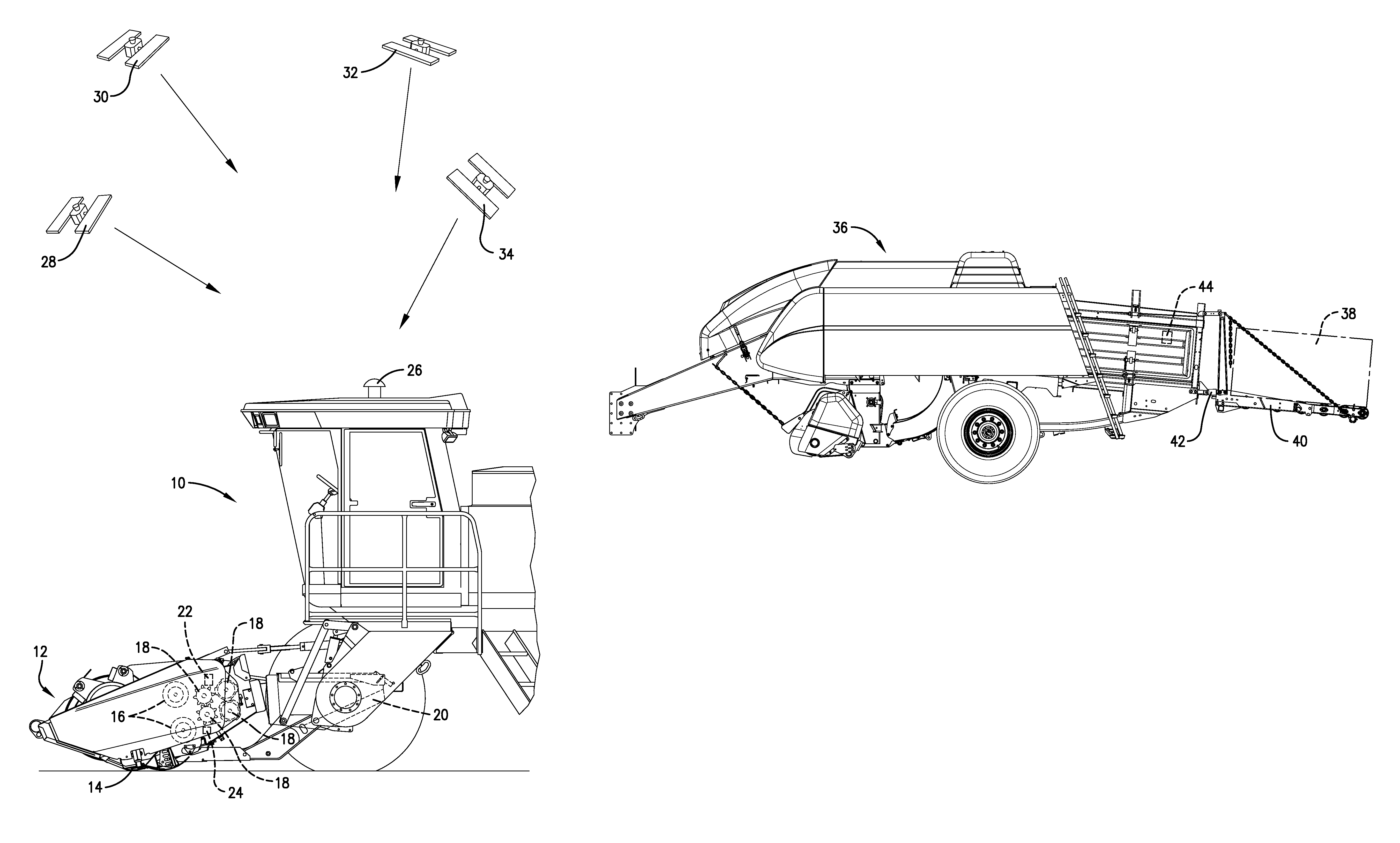
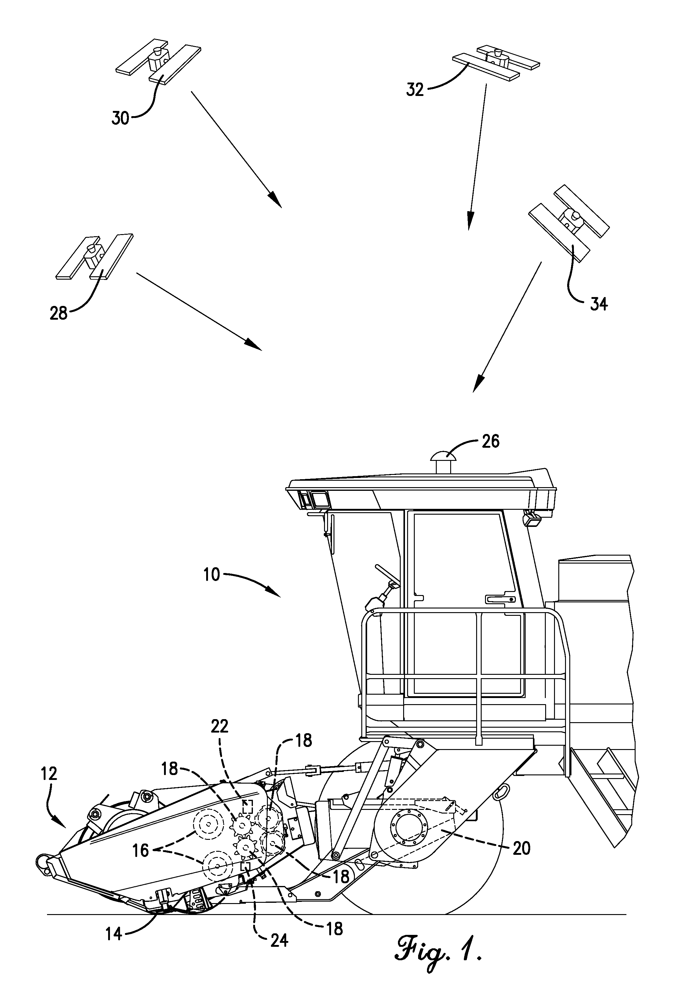
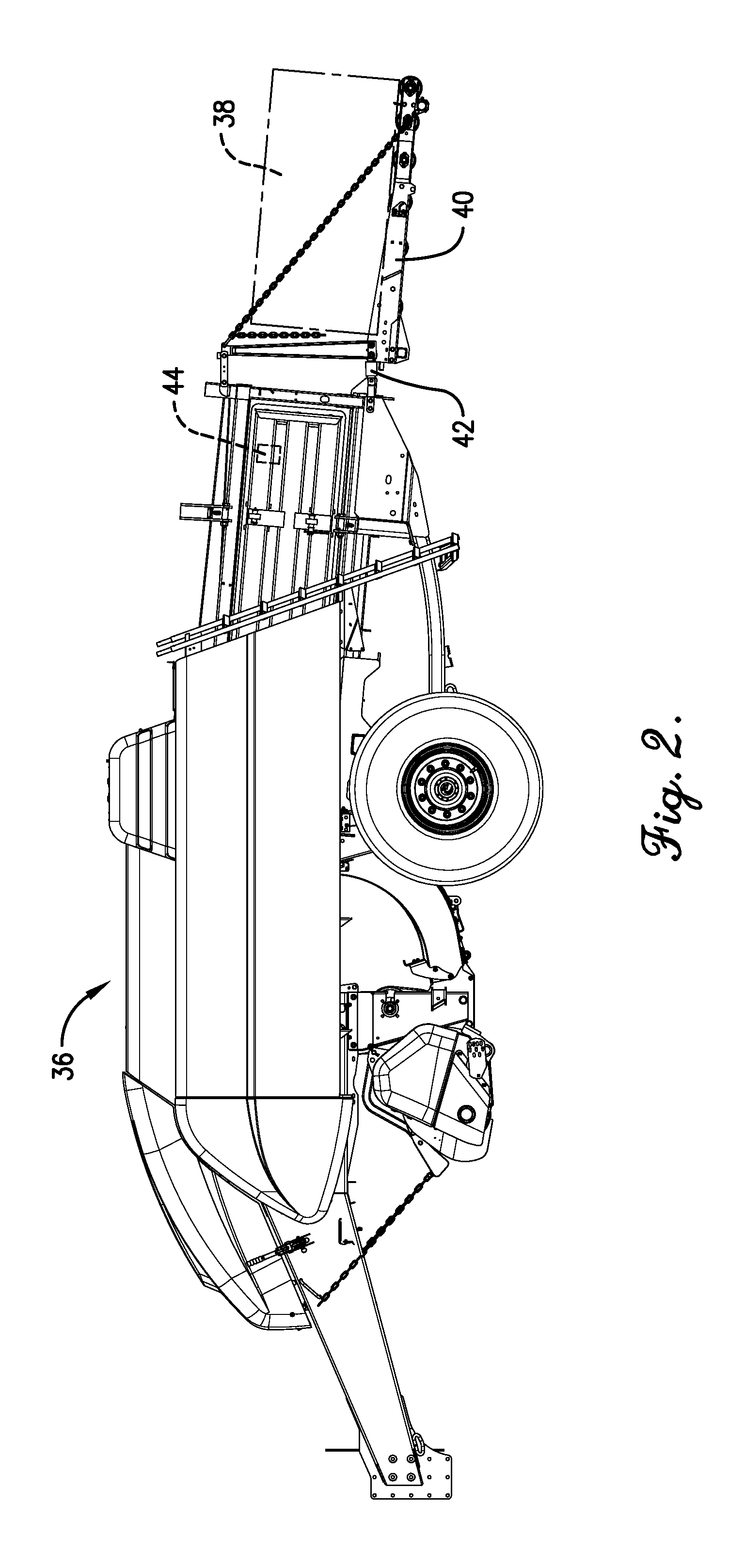
[0010]FIG. 1 illustrates a windrower 10 that is adapted to sever standing forage crop materials from the field, condition the cut materials, and return them to the field in a windrow or swath for drying. In the particular embodiment illustrated in the drawing, windrower 10 happens to comprise a self-propelled windrower (it could just as easily be a pull-type machine). Windrower 10 has a header 12 having the usual reciprocating or rotary cutter mechanism 14 for cutting the standing crop as the machine advances, center-gathering auger mechanism 16 (a pair of augers in this embodiment) for converging the cut crop material...


PUM


Abstract

Dry yield for baled forage crop materials may be obtained for specific cut locations in the field by allocating the overall average baled dry yield for the entire field to the specific cut locations in accordance with the cut yield at such locations. Information obtained from a position sensor and one or more crop volume sensors on the windrower or mower is later combined with information obtained from a weight sensor on the baler to arrive at a specific location dry yield report for the baled product.

Description

TECHNICAL FIELD[0001]The present invention relates to measuring the yield of harvested crops and, more particularly, to measuring the dry yield of baled forage crops for specific cut locations within a field after the crops have been cut from the ground, allowed to dry, and then baled into suitable bale packages for further handling.BACKGROUND AND SUMMARY[0002]Various methods have heretofore been suggested for measuring the cut yield of forage crop materials at specific locations within the field as the cut materials pass through the machine that severs them from the ground. However, due to the unique nature of forage crop materials and the many variables that exist in the size, shape and density of the stalks, stems, and mat or stream moving through the machine, it is extremely difficult to determine actual cut yield in meaningful units of measurement with any degree of accuracy. At best, the data obtained from prior methods could thus only be relied upon to provide the user with y...

Claims


Application Information

Patent Timeline
Patent Type & Authority Patents(United States)
IPC IPC(8): A01D34/00A01D41/127A01F15/08
CPCA01D34/006A01D41/127A01F2015/0891
Inventor CLARK, STANLEY, R.
Owner AGCO CORP
Learn More