Vacuum cleaner

a vacuum cleaner and vacuum cleaner technology, applied in vacuum cleaners, cleaning equipment, domestic applications, etc., can solve the problems of inconvenience for users, and achieve the effect of smooth chang

Active Publication Date: 2016-02-09
SAMSUNG ELECTRONICS CO LTD
View PDF7 Cites 17 Cited by
  • Summary
  • Abstract
  • Description
  • Claims
  • Application Information

AI Technical Summary

Benefits of technology

[0008]Therefore, it is an aspect of the present disclosure to provide a vacuum cleaner capable of changing a direction in a smoother way.
[0043]As described above, the vacuum cleaner according to an embodiment of the present disclosure freely rotates the extension frame in forward, backward, leftward, and rightward directions through a structure in which the wheel assembly, the first housing, and the second housing are installed, so that movement and rotation directions of the vacuum cleaner can be smoothly changed.
[0044]Further, the wheel assembly is rotated by leftward or rightward rotation of the extension frame, and thus forms an angle with the head unit, so that the vacuum cleaner can be rotated with a smaller radius of rotation.

Problems solved by technology

However, the structure of the conventional vacuum cleaners is such that while a forward and backward movement of the vacuum cleaner may be accomplished by a user, other movements such as left or right, are more difficult and cause inconvenience to a user.

Method used


Image

  • Vacuum cleaner
  • Vacuum cleaner
  • Vacuum cleaner

Examples


first embodiment

[0066]Hereinafter, a vacuum cleaner according to the present disclosure will be described in detail with reference to the accompanying drawings.

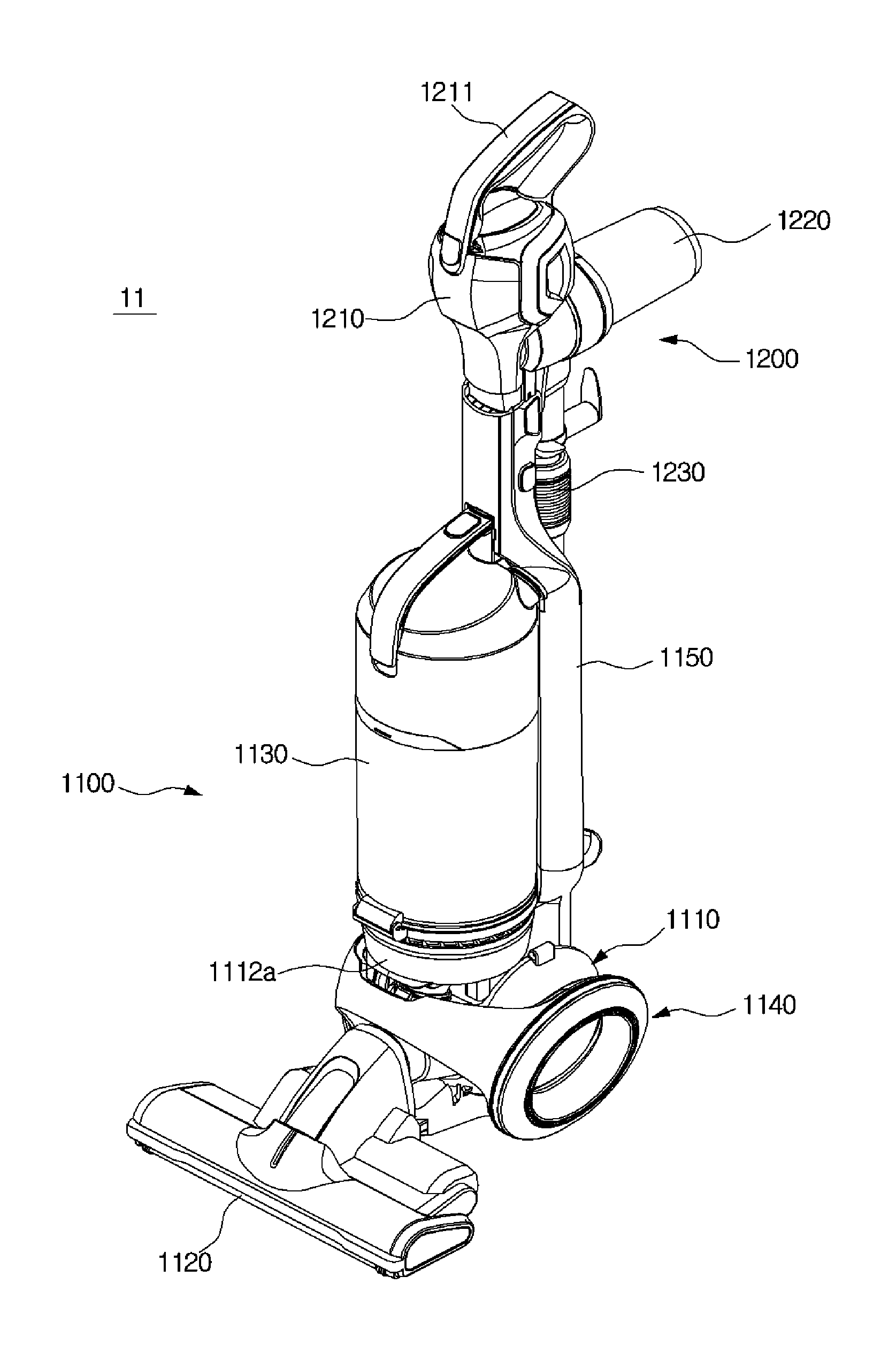
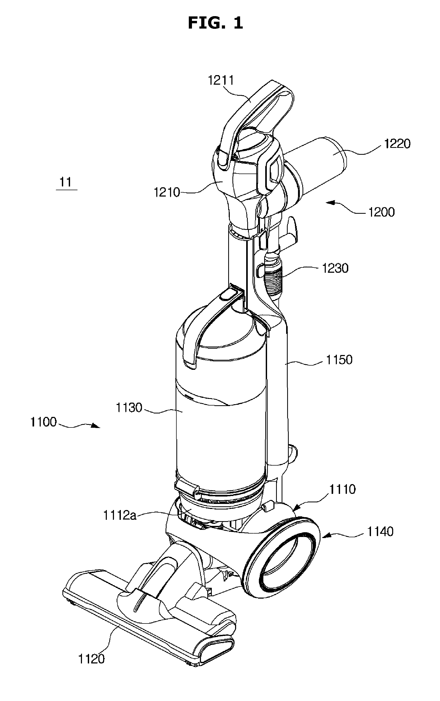
[0067]As illustrated in FIG. 1, a vacuum cleaner 11 according to a first embodiment of the present disclosure includes an upright cleaner module 1100 enabling a user to clean a floor in an upright mode, and a handy cleaner module 1200 that is removably installed on the upright cleaner module 1100 and enables the user to do cleaning in a handy mode after being decoupled from the upright cleaner module 1100.

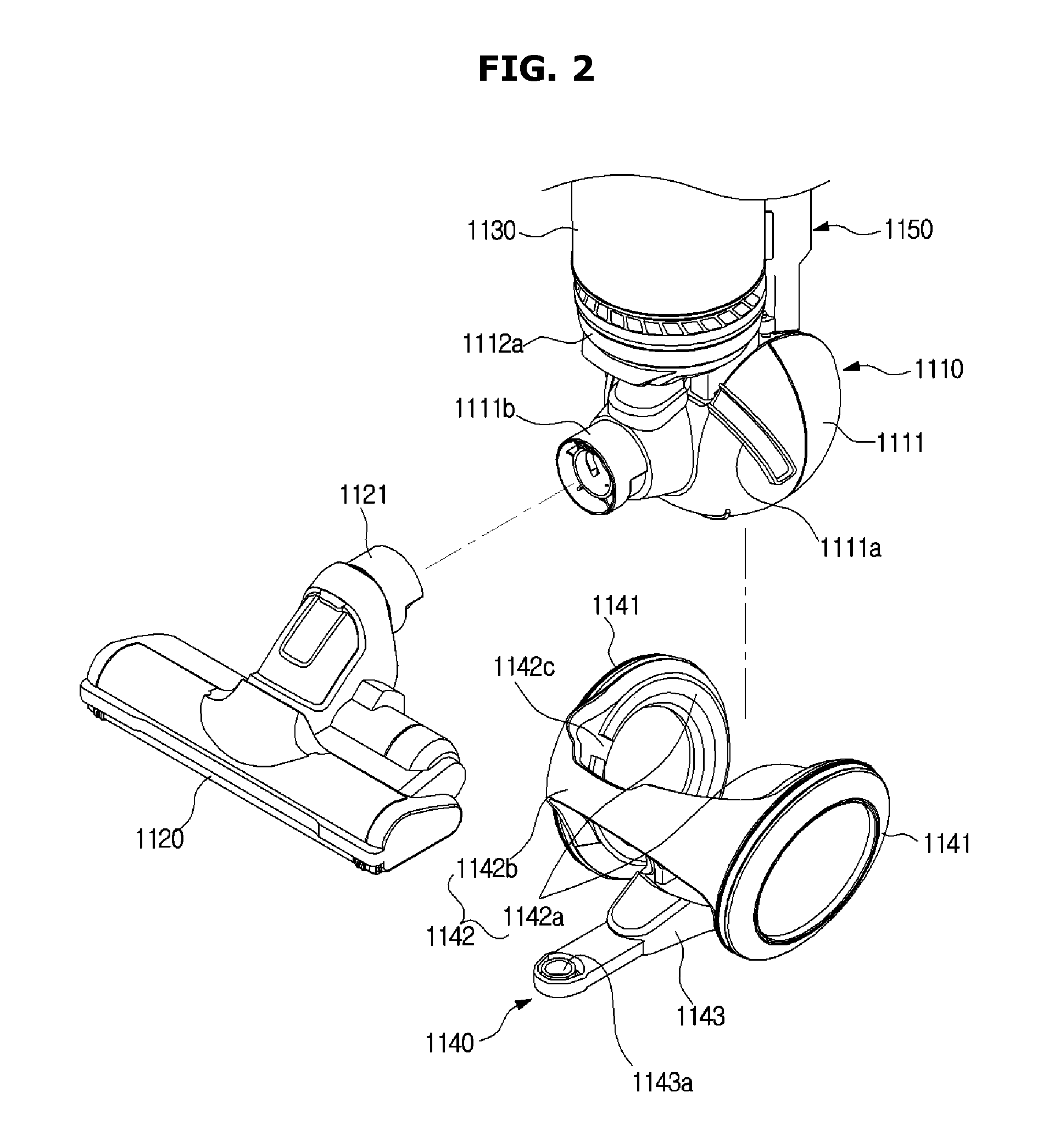
[0068]The upright cleaner module 1100 includes an upright main body 1110 in which an upright fan motor 1170 (see FIG. 8) generating a suction force when cleaning is done in the upright mode is housed, a head unit 1120 that is connected to a front side of the upright main body 1110, comes into contact with a floor to be cleaned, and suctions dust on the floor along with air, an upright dust collection unit 1130 that is mounted on an upper si...

second embodiment

[0105]That is, the present disclosure as illustrated in FIGS. 13 and 14 can obtain an effect of reducing the rotational radius of the vacuum cleaner without configurations corresponding to the guide rails 1111a and the guides 1142c.

[0106]In detail, as illustrated in the figures, when the user rotates the extension frame 1150 to the left or right side with the extension frame 1150 inclined toward a rear upper side, the extension frame 1150 and the head unit 1120 form an angle due to the leftward / rightward rotation of the extension frame 1150. Thereby, the rotational radius of the vacuum cleaner is reduced. In this case, the head unit 1120 is preferably fixedly installed at the front side of the wheel assembly 1140.

third embodiment

[0107]Hereinafter, a vacuum cleaner according to the present disclosure will be described in detail with reference to the drawings.

[0108]As illustrated in FIGS. 15 and 16, a vacuum cleaner 21 according to a third embodiment of the present disclosure includes an upright cleaner module 2100 enabling a user to clean a floor, a pipe module 2200 that is removably installed on the upright cleaner module 2100 and enables the user to clean various places which the upright cleaner module 2100 cannot clean after being decoupled from the upright cleaner module 2100, and a connecting hose 2300 that connects the upright cleaner module 2100 and the pipe module 2200 and causes a suction force generated from the upright cleaner module 2100 to be transmitted to the pipe module 2200.

[0109]The upright cleaner module 2100 includes an upright main body 2110 in which a fan motor (not shown) generating a suction force when a floor is cleaned is housed, a head unit 2120 that is connected to a front side of...


PUM


Abstract

A vacuum cleaner that includes an upright main body, an upright fan motor generating a suction force, and a wheel assembly that is mounted on the upright main body and guides movement and rotation of the upright main body. The upright main body includes a first housing that is installed on the wheel assembly so as to be rotatable in a leftward / rightward direction, and a second housing that is installed in the first housing so as to be rotatable in a forward / backward direction. The vacuum cleaner can be moved and rotated by freely moving an extension frame extending upward from the second housing in forward, backward, leftward, and rightward directions.

Description

CROSS-REFERENCE TO RELATED APPLICATIONS[0001]This application claims the benefit of Korean Patent Application Nos. 10-2013-0106744, 10-2014-0053518 and 10-2014-0056772, filed on Sep. 5, 2013, May 2, 2014 and May 12, 2014, respectively, in the Korean Intellectual Property Office, the disclosures of which are incorporated herein by reference.BACKGROUND[0002]1. Field[0003]Embodiments of the present disclosure relate to a vacuum cleaner capable of changing a direction in a smoother way.[0004]2. Description of the Related Art[0005]In general, vacuum cleaners are appliances designed to do cleaning by suctioning dust along with air using a suction force generated from a fan rotated by a motor, separating the dust included in the suctioned air from the air, and collecting the separated dust.[0006]Such vacuum cleaners include a main body with a fan motor generating a suction force, a head unit that is disposed in the front of the main body and suctions dust from a floor along with air, a han...

Claims


Application Information

Patent Timeline
Patent Type & Authority Patents(United States)
IPC IPC(8): A47L5/28A47L9/00
CPCA47L5/28A47L9/009
Inventor KIM, TAE GWANGKIM, TAK SOOKWON, OH KYUYOO, DONG HUNJEONG, JOO SEOKLIM, TAE WOONLEE, BYUNG JOJUNG, YUN WONCHO, JEONG HEEHONG, JUNG HOON
Owner SAMSUNG ELECTRONICS CO LTD
Why Eureka
Try Eureka