
Motion Transmission Apparatus with a Chain

Inactive Publication Date: 2011-02-03
HIWIN TECH
View PDF23 Cites 7 Cited by
  • Summary
  • Abstract
  • Description
  • Claims
  • Application Information

AI Technical Summary

Benefits of technology

The primary object of the present invention is to provide a chain which is capable of keeping contacting the rolling element when moving in a twisted and / or curved endless circulation path, furthermore, the chain is capable of being twisted or turned and can be prevented from interfering with the inner surface of the endless circulation path.
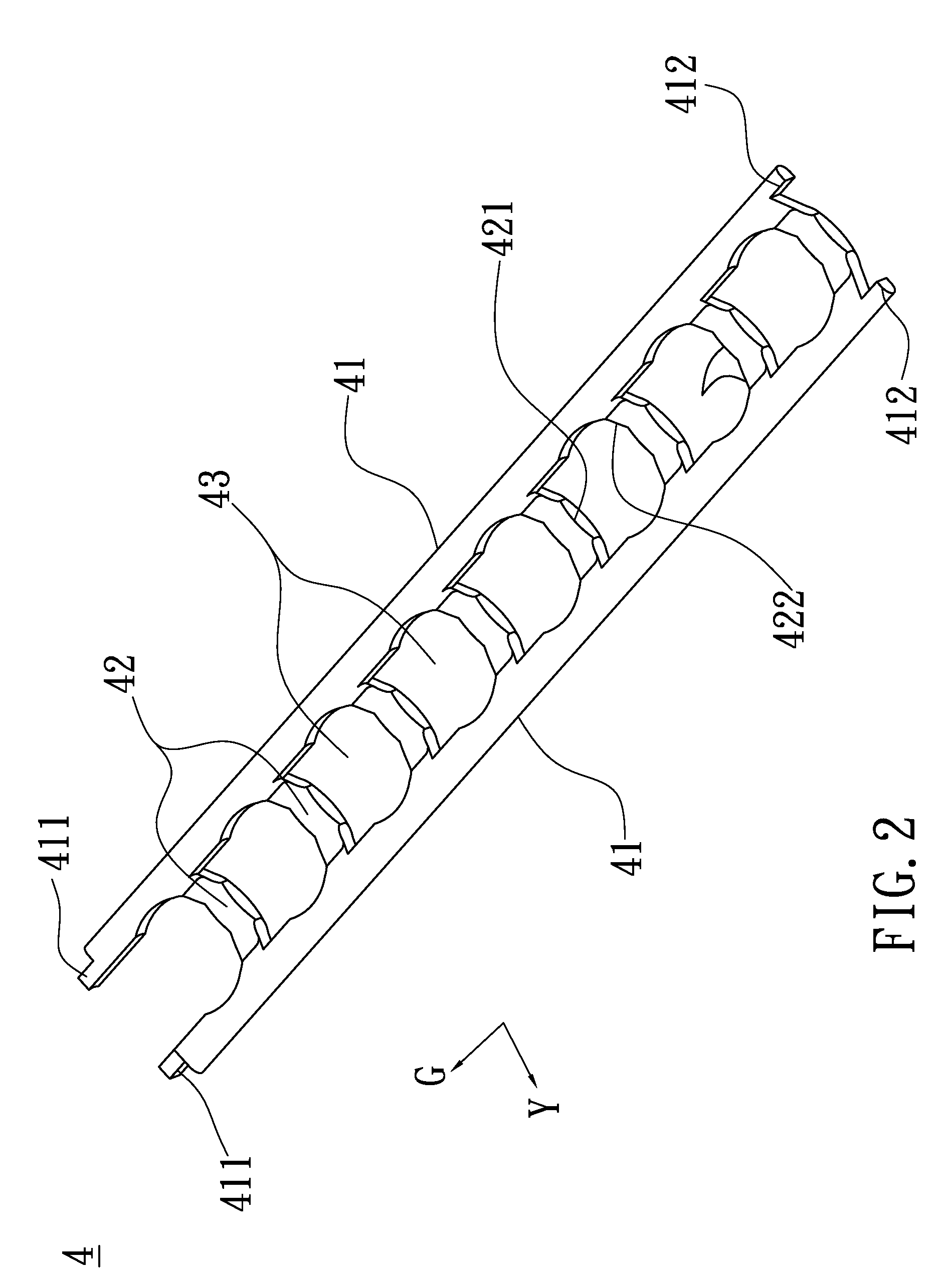
Each of the spacers is provided at one side thereof in a longitudinal direction thereof with a first retaining surface, and at another side thereof with more than one (or two) second retaining surfaces (which can be arc-shaped or polygonal-shaped), the first and second retaining surfaces are all in contact with the rolling elements. All positions where the first and second retaining surfaces are in contact with the rolling elements are in the same plane. More than one oil-storage space exists in each of the receiving spaces for providing sufficient lubricant oil to the rolling elements, after the rolling elements are received in the receiving spaces. The chain is approximately rectangular-shaped. The height of each of the spacers is 0.35-0.45, and optimally 04, of a diameter of the rolling elements. The height of each of the spacers is optimally 0.4 of the diameter of the rolling elements, and the height of each of the links is optimally equal to the height of the spacers. Therefore, as compared to the conventional chain structure, the chain of the present invention can move in a smoother way when moving in a twisted and / or curved endless circulation path, because the spacers of the conventional chain structure are relatively high and in arc-shaped line contact with the rolling elements, and as a result, the spacers of the conventional chain structure will be in contact with the rolling elements via a single edge when moving in a twisted and / or curved endless circulation path, so that the spacers are unevenly stressed, which will accelerate the wear of the spacers and reduce the service life of the chain.
Finally, after the chain of the present invention is installed in the endless circulation path, a first and a second ends of the chain can be jointed to each other (by convex and concave engagement means, interference fit, ultrasonic welding, glue and etc) to form an endless chain, so as to prevent both ends of the chain from interfering with the endless circulation path and accordingly ensure a smooth circulation.

Problems solved by technology

Although the transmission apparatus with a chain has a lot of advantages, it might stop the rolling elements from moving smoothly while reducing the precision of the rolling elements' motion and causing severe damage if the structural design of the chain is not in line with the motion track of the motion transmission apparatus.
This chain structure is in arc-shaped line contact with the rolling elements, and it is impossible for the chain to be turned or twisted when the motion transmission apparatus is moving along its complicated motion track because these rings will be subjected to pressure and tensile deformation and cause interference with the inner surface of the motion track, which is likely to cause rupture of the chain and bad circulation of the rolling elements.
When the chain structure moves along the twisted or curved endless circulation path, the concave of the spacers is unable to keep in frill contact with the rolling elements.
Furthermore, when moving through a curved path, the deformation of the chain will make the spacers shift toward the inner side of the curved path, as a result, the spacers will rub against the inner surface of the path, causing friction, which will further result in a bad circulation of the rolling elements.

Method used


Image

  • Motion Transmission Apparatus with a Chain
  • Motion Transmission Apparatus with a Chain
  • Motion Transmission Apparatus with a Chain

Examples


Embodiment Construction

The present invention will be clearer from the following description when viewed together with the accompanying drawings, which show, for purpose of illustrations only, the preferred embodiment in accordance with the present invention.

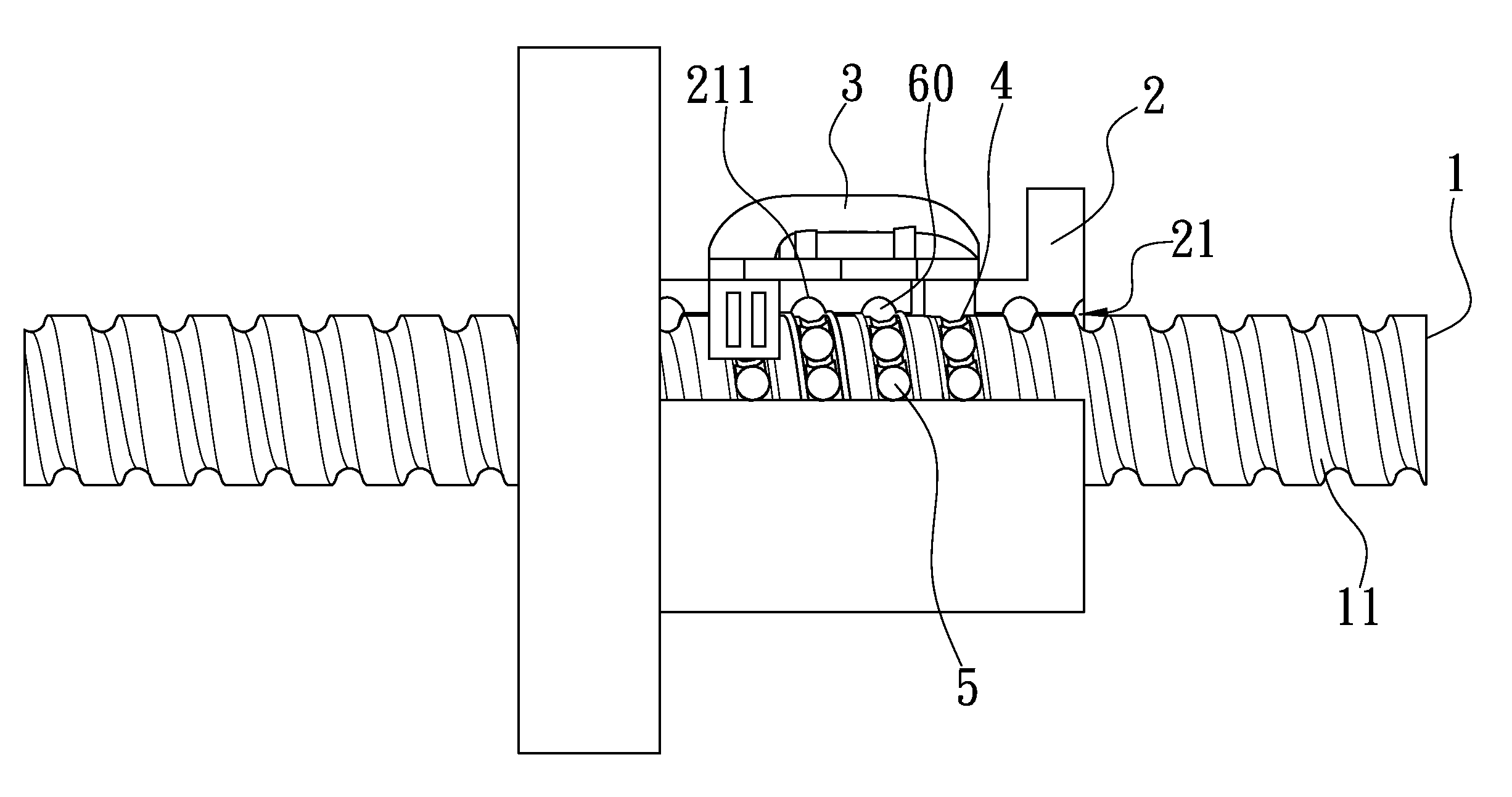
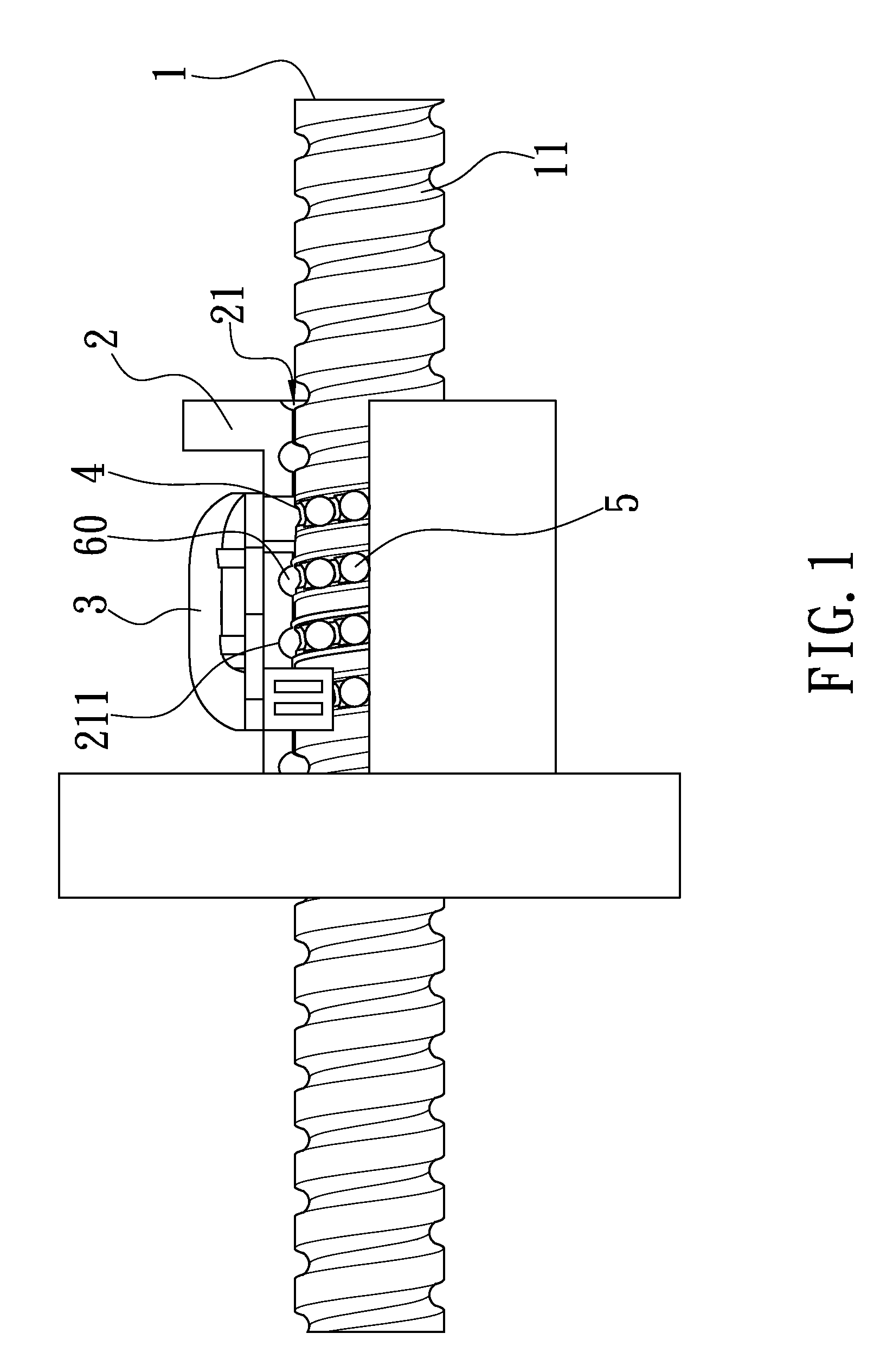
Referring to FIGS. 1-5, a motion transmission apparatus with a chain in accordance with the present invention comprises: an elongated shaft 1, a movable member 2, at least a circulating member 3, a plurality of rolling elements 5, and a chain 4.

The elongated shaft 1 is defined with a rolling groove 11.

The movable member 2 is defined with an accommodation portion 21 for insertion of the elongated shaft 1, and in the accommodation portion 21 is formed a rolling groove 211 for cooperating with the rolling groove 11 of the elongated shaft 1 to form a load path 60.

The circulating member 3 is fixed on the movable member 2 and defined with a return path (not shown) which is connected to the load path 60 to form an endless circulation path.

The rolling elements...


PUM


Abstract

A motion transmission apparatus with a chain, wherein the chain comprises a plurality of spacers and two links two links at both sides of the respective spacers for connecting spacers together. The spacers are equidistantly spaced from one another by a receiving space which is longitudinally asymmetrical and provided for holding rolling elements.

Description

BACKGROUND OF THE INVENTION1. Field of the InventionThe present invention relates to a motion transmission apparatus, and more particularly to a motion transmission apparatus with a chain.2. Description of the Prior ArtCurrently a type of motion transmission apparatus with a chain has been invented to reduce the noise of the motion transmission apparatus and the friction between the rolling elements, wherein the rolling elements are received in the chain so that they can be prevented from impacting one another, thus reducing the generation of noise. Furthermore, the rolling elements are prevented from contacting each other so that the friction between the rolling elements is also reduced, which, as a result, extends the service life while ensuring a precise and smooth operation of the chain.Although the transmission apparatus with a chain has a lot of advantages, it might stop the rolling elements from moving smoothly while reducing the precision of the rolling elements' motion and ...

Claims


Application Information

Patent Timeline
IPC IPC(8): F16H25/22
CPCF16H25/2238Y10T74/19777F16C33/3825
Inventor HSU, PO-CHUANCHEN, YAN-YU
Owner HIWIN TECH
Learn More