Method and apparatus for magnetic brush retraction in electrophotographic system

a technology of electrophotographic system and magnetic brush, which is applied in the direction of electrographic process apparatus, instruments, optics, etc., can solve the problems of inability to position toner particles to contact, reduced useful life of toner cartridge, and inability to meet the needs of customers,

Active Publication Date: 2016-02-09
LEXMARK INT INC
View PDF1 Cites 1 Cited by
  • Summary
  • Abstract
  • Description
  • Claims
  • Application Information

AI Technical Summary

Benefits of technology

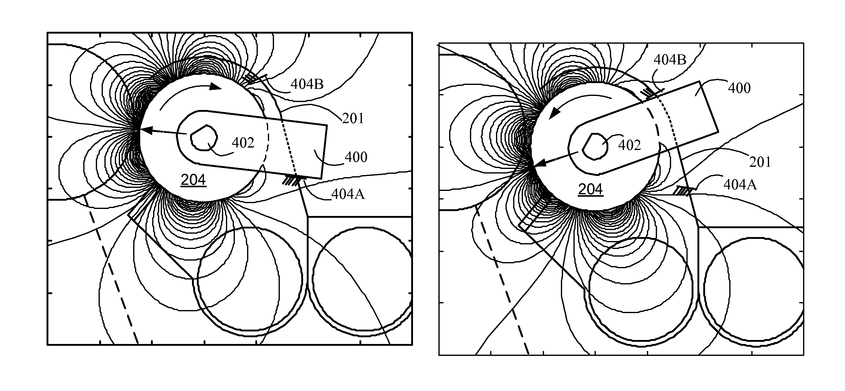
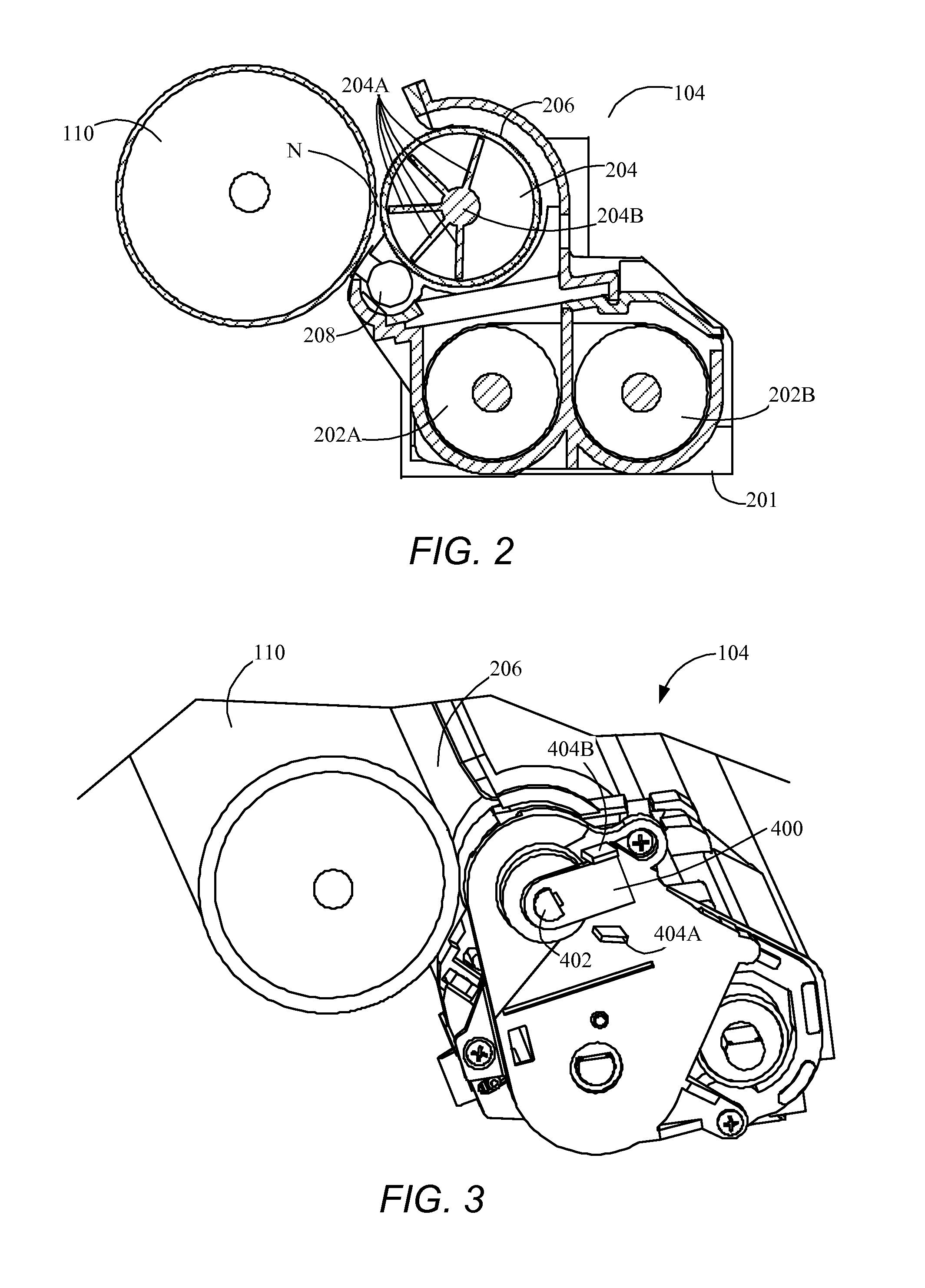
[0009]In an example embodiment, the magnetic structure is rotated between the first and second positions by a motor, solenoid or the like. In another example embodiment, the magnetic structure is substantially freely rotatable about a shaft and is coupled to the endless sleeve via attractive forces with the carrier beads on the sleeve such that the magnetic structure rotates with the endless sleeve between the first and second positions. In this embodiment, the developer apparatus further includes an extension member having a first end connected to the shaft and a distal end. The extension member rotates with the shaft and thereby with the magnetic structure. The developer apparatus further includes a pair of stop members extending from or within the housing in proximity to the distal end of the extension member. The stop members are positioned to contact the distal end of the extension member and thereby serve to limit the amount of rotation of the magnetic structure to be between the first and second positions when the magnetic structure moves with the endless sleeve.

Problems solved by technology

This toner waste reduces the useful life of a toner cartridge since it represents an undesirable draw of toner for printing.
For color laser printers, the cost to the customer of background toner when printing a white page can, in some circumstances, approach or exceed the cost of a sheet of paper.
As a result, toner particles are not positioned to contact the adjacent photoconductive member of the imaging system to be transferred thereto during times when toner development is not being performed.

Method used


Image

  • Method and apparatus for magnetic brush retraction in electrophotographic system
  • Method and apparatus for magnetic brush retraction in electrophotographic system
  • Method and apparatus for magnetic brush retraction in electrophotographic system

Examples


Embodiment Construction

[0016]It is to be understood that the present disclosure is not limited in its application to the details of construction and the arrangement of components set forth in the following description or illustrated in the drawings. The present disclosure is capable of other embodiments and of being practiced or of being carried out in various ways. Also, it is to be understood that the phraseology and terminology used herein is for the purpose of description and should not be regarded as limiting. The use of “including,”“comprising,” or “having” and variations thereof herein is meant to encompass the items listed thereafter and equivalents thereof as well as additional items. Unless limited otherwise, the terms “connected,”“coupled,” and “mounted,” and variations thereof herein are used broadly and encompass direct and indirect connections, couplings, and mountings. In addition, the terms “connected” and “coupled” and variations thereof are not restricted to physical or mechanical connec...


PUM


Abstract

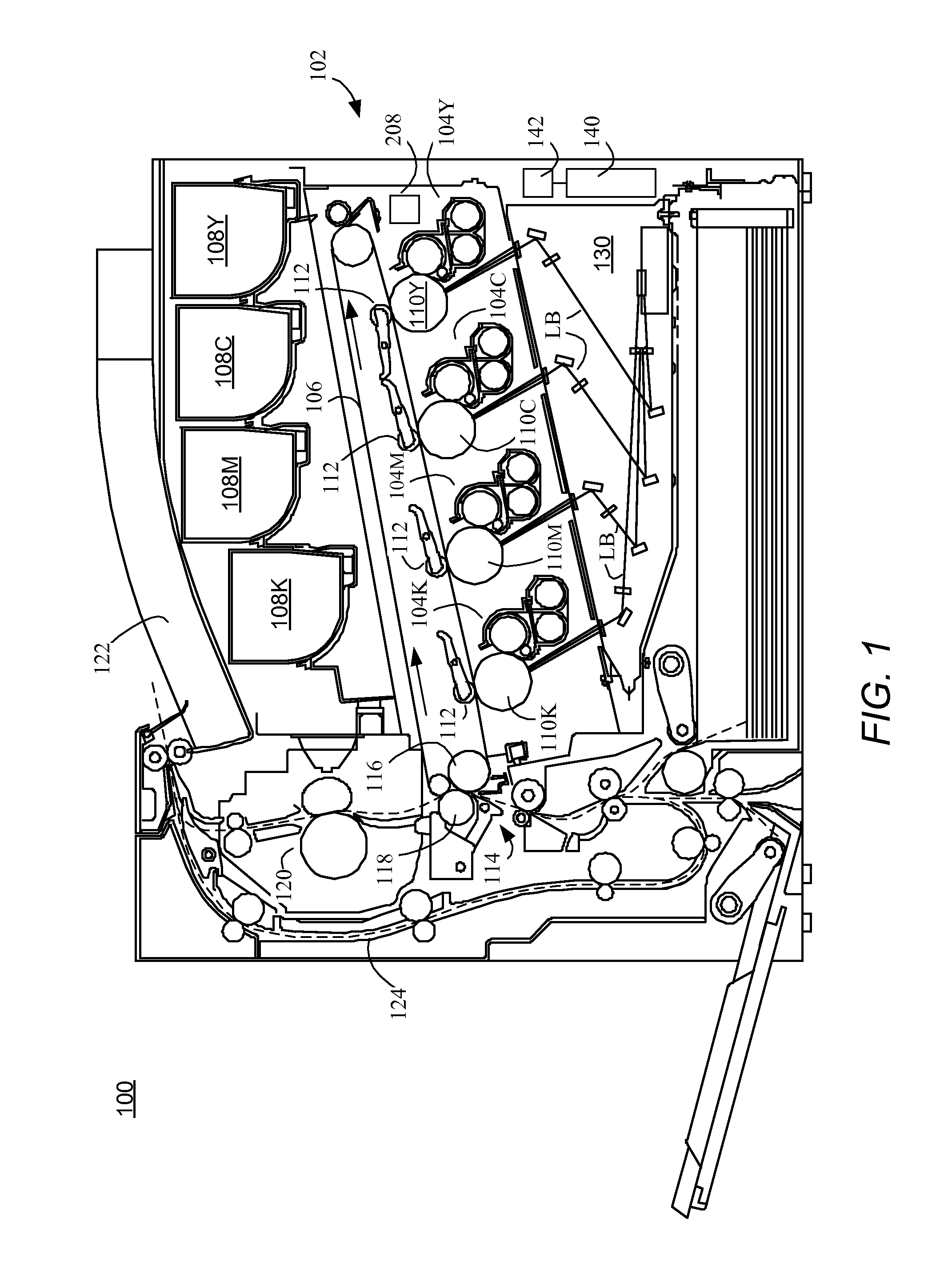
A method and apparatus for retracting a magnetic brush in an imaging device. The apparatus includes a housing containing carrier beads and toner particles; a magnetic structure at least partly disposed within the housing and generating at least one magnetic field; and an endless sleeve disposed around and rotatable about the magnetic structure, at least a portion of the sleeve extending from the housing. During toner development, the magnetic structure is in a first position for developing a magnetic brush of the carrier beads and toner particles along the portion of the sleeve extending from the housing which forms a developer nip with a photoconductor, and during a period of time when toner development is not to be performed, the magnetic structure is in a second position for retracting the magnetic brush by causing the carrier beads to be positioned against the portion of the endless sleeve extending from the housing forming the developer nip.

Description

CROSS REFERENCES TO RELATED APPLICATIONSSTATEMENT REGARDING FEDERALLY SPONSORED RESEARCH OR DEVELOPMENT[0001]None.REFERENCE TO SEQUENTIAL LISTING, ETC[0002]None.BACKGROUND[0003]1. Field of the Disclosure[0004]The present disclosure relates generally to developing a magnetic brush for transferring toner to a photoconductive member, and particularly to selectively retracting the developed magnetic brush from contact with the photoconductor to substantially prevent background toner development.[0005]2. Description of the Related Art[0006]Electrophotography selectively develops toner to the photoconductor by discharging areas of the photoconductor that correspond to areas to be colored and leaving other areas charged so as to prevent toner development in those “white” areas. For negatively charged toner, these white areas are created by providing a photoconductor charge that is more negative than the developer bias. This difference between the photoconductor and developer biases is call...

Claims


Application Information

Patent Timeline
Patent Type & Authority Patents(United States)
IPC IPC(8): G03G15/09
CPCG03G15/0921
Inventor CAMPBELL, ALAN STIRLINGDENTON, GARY ALLEN
Owner LEXMARK INT INC
Why Eureka
Try Eureka