Image forming apparatus

a technology of forming apparatus and forming gear, which is applied in the direction of thin material processing, article separation, article delivery, etc., can solve the problems of restricted movement of intermediate gear along the inner surface of intermediate gear bearings, and achieve the effect of improving the manufacturing of precision components

Inactive Publication Date: 2006-04-20
FUNAI ELECTRIC CO LTD
View PDF10 Cites 0 Cited by
  • Summary
  • Abstract
  • Description
  • Claims
  • Application Information

AI Technical Summary

Benefits of technology

[0016] An object of the present invention is to provide an image forming apparatus in which the conveyance of pa...

Problems solved by technology

Therefore, the movement of the intermediate gear along the i...

Method used


Image

  • Image forming apparatus
  • Image forming apparatus
  • Image forming apparatus

Examples


first embodiment

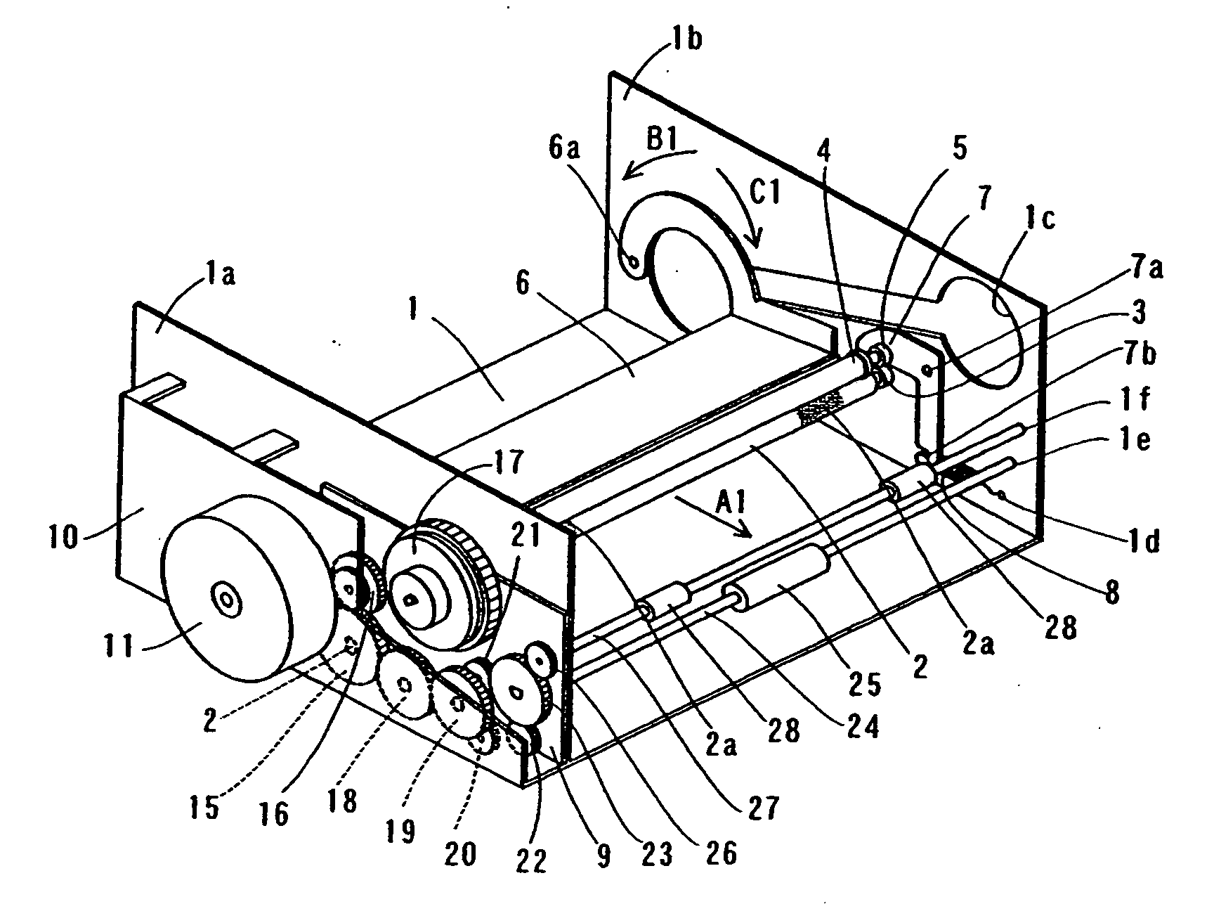
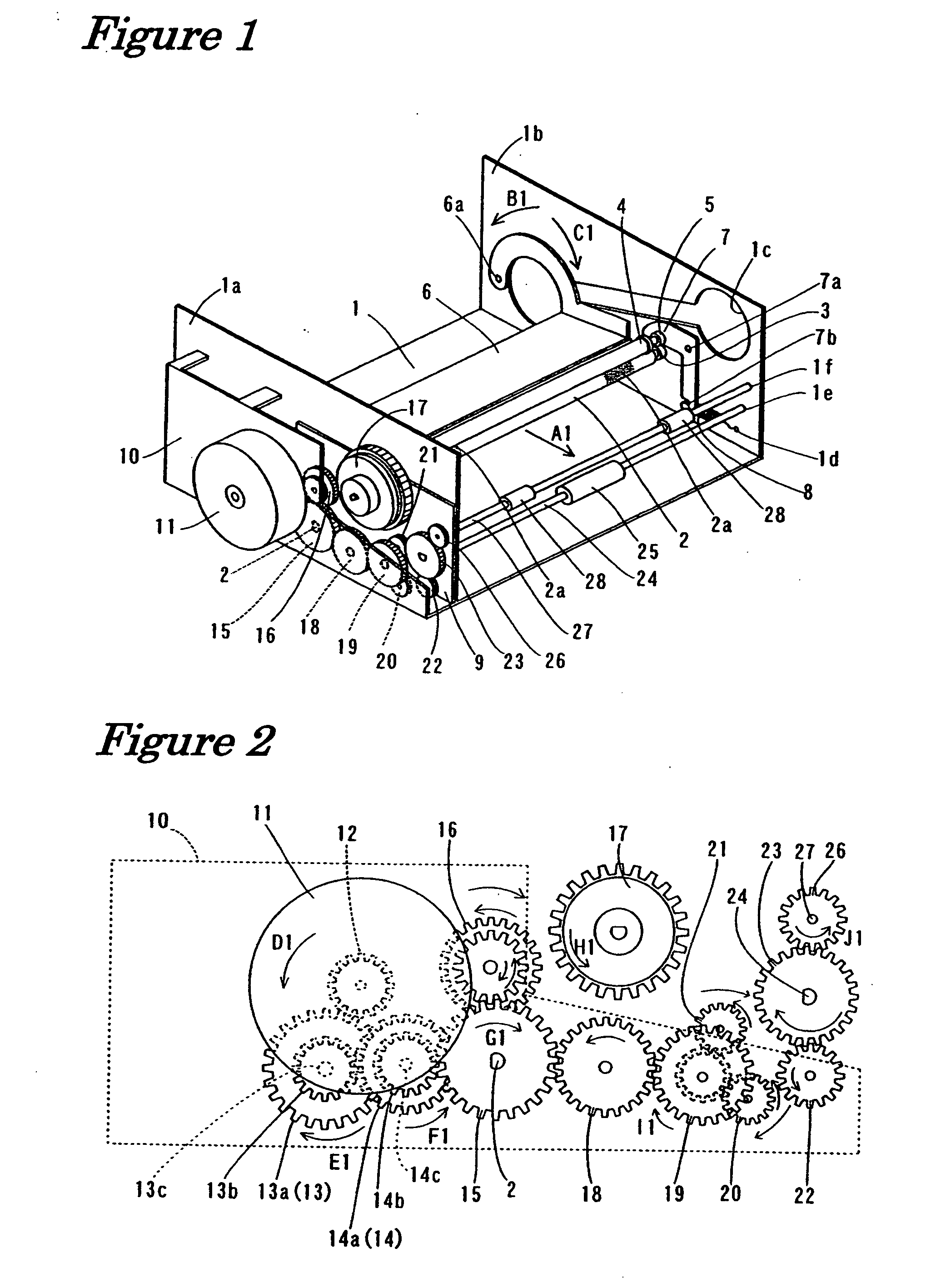
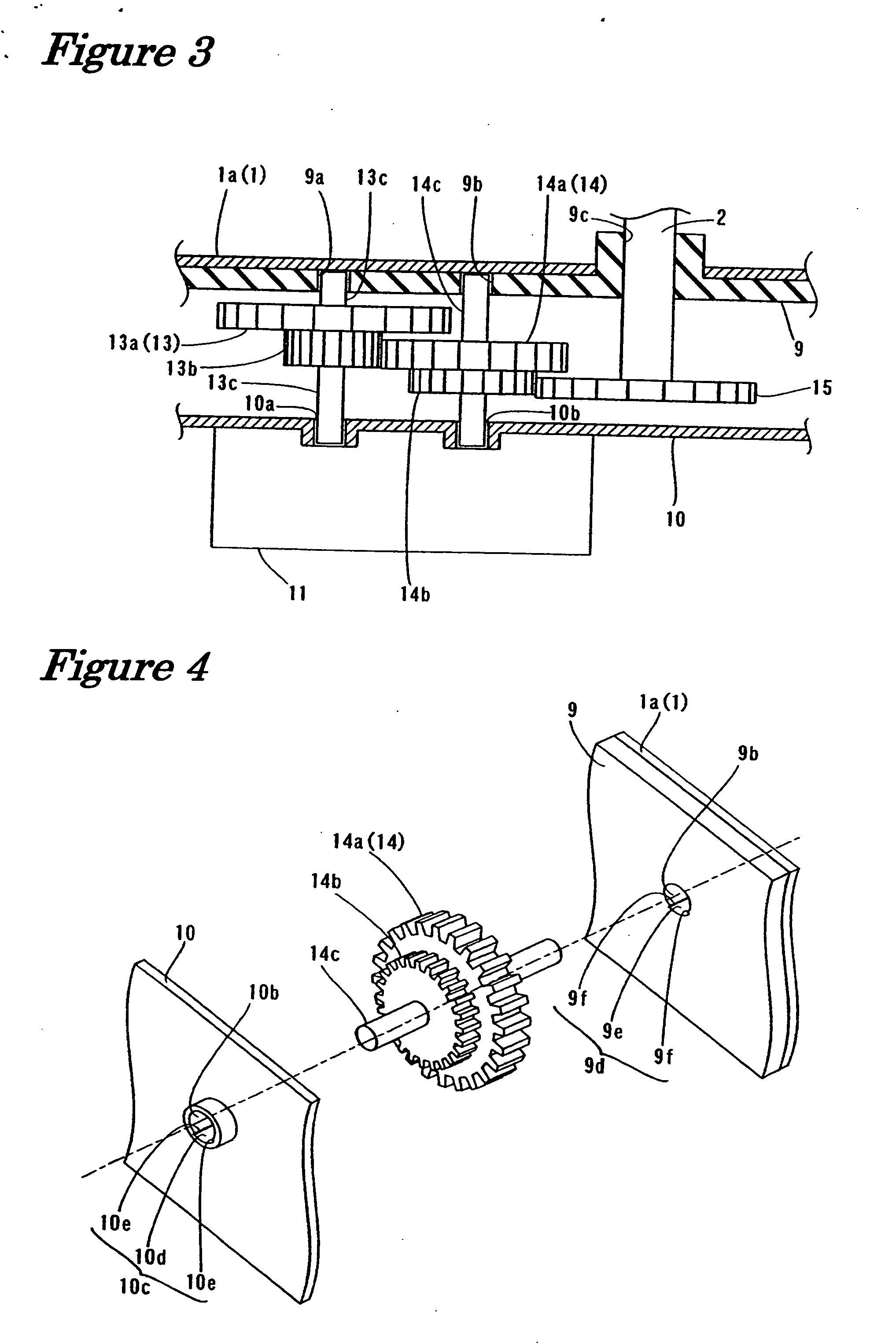
[0053]FIG. 1 is a perspective view showing the general structure of a heat transfer printer according to the first embodiment of the present invention. FIG. 2 is a front view showing the motor and gears in the heat transfer printer according to the first embodiment of the present invention shown in FIG. 1. FIG. 3 is a plan view showing the motor and gears in the heat transfer printer according to the first embodiment of the present invention shown in FIG. 1. FIGS. 4 through 7 are diagrams showing the details of the structure of the heat transfer printer according to the first embodiment of the present invention shown in FIG. 1. The structure of the heat transfer printer according to the first embodiment of the present invention will now be described with reference to FIGS. 1 through 7. In the first embodiment, a heat transfer printer is described as an example of the image forming apparatus of the present invention.

[0054] As shown in FIGS. 1 and 2, the heat transfer printer accordi...

second embodiment

[0078]FIG. 8 is an exploded schematic perspective view showing the structure in which the intermediate gear is mounted in the heat transfer printer according to the second embodiment of the present invention. FIG. 9 is a detailed view showing the intermediate gear in the heat transfer printer according to the second embodiment shown in FIG. 8. FIG. 10 is a partial enlarged view showing the intermediate gear bearing of the motor bracket in the heat transfer printer according to the second embodiment shown in FIG. 8. FIG. 11 is a partial enlarged view showing the intermediate gear bearing of the side plate in the heat transfer printer according to the second embodiment shown in FIG. 8.

[0079] In the second embodiment, an example will be described in which the support units of the intermediate gear bearings are provided with support surfaces that support the axle of the intermediate gear with an arcuate surface, unlike the first embodiment. The structures in the second embodiment, othe...


PUM

PropertyMeasurementUnit
Angleaaaaaaaaaa
Forceaaaaaaaaaa
Diameteraaaaaaaaaa

Abstract

An image forming apparatus has a chassis, a feed roller rotatably supported by the chassis, a feed roller gear relatively unrotatably coupled to the feed roller, a motor that drives the feed roller, a drive gear that receives driving force from the motor, and an intermediate gear having a gear portion that engages the drive gear and the feed roller gear and an axle portion that is rotatably supported to the chassis via intermediate gear bearings. At least one of the intermediate gear bearings includes a substantially circular inner surface and a stepped portion that is depressed from the circular inner surface. The axle portion of the intermediate gear is supported by the stepped portion while the intermediate gear transmits driving force the motor from the drive gear to the feed roller gear during printing.

Description

BACKGROUND OF THE INVENTION [0001] 1. Field of the Invention [0002] The present invention relates to an image forming apparatus. More specifically, the present invention relates to an image forming apparatus having an intermediate gear bearing that rotatably supports an intermediate gear for transmitting drive force. [0003] 2. Background Information [0004] In conventional practice, structures having intermediate gear bearings that rotatably support intermediate gears are known. [0005] Also, heat transfer printers are conventionally known as an example of image forming apparatuses. The structure of the heat transfer printer according to a conventional example will now be described with reference to FIGS. 13 through 16. [0006] A heat transfer printer is generally equipped with a motor for driving various rollers. Such motor generally has a motor gear that engages a drive gear, such as a drive gear 113 shown in FIG. 14. The motor transmits the torque to a feed roller 115 via the drive ...

Claims


Application Information

Patent Timeline
IPC IPC(8): B65H5/00B65H5/02
CPCB65H3/0669B65H2401/115B65H2403/42B65H2401/11
Inventor SAWAI, KUNIO
Owner FUNAI ELECTRIC CO LTD
Why Eureka
Try Eureka