Detecting probe mounting device

a technology for mounting devices and detecting probes, which is applied in the direction of instruments, machine supports, fluid pressure measurement, etc., can solve the problems that the downtime for servicing and/or replacing one or more detecting probes cannot be postponed, and the downtime for servicing and/or replacing detecting probes is relatively high, so as to reduce the complexity of servicing and reduce the time. , the effect of reducing downtime and costs

Active Publication Date: 2016-02-16
SIEMENS ENERGY GLOBAL GMBH & CO KG
View PDF17 Cites 1 Cited by
  • Summary
  • Abstract
  • Description
  • Claims
  • Application Information

AI Technical Summary

Benefits of technology

[0005]It is an object of the present invention to overcome afore-said disadvantages of already known machines with detecting probes. In particular, it is an object of the present invention to provide a detecting probe mounting device, a casing comprising such a detecting probe device as well as the respective machine with such a casing and a method for servicing and / or replacing at least one detecting probe, which are all able to provide servicing and / or replacing of at least one detecting probe in a reduced time and therefore with reduced downtime and costs. Moreover, it is an objective of the present invention to reduce the complexity for servicing and / or replacing the detecting probes of machines with rotating members.

Problems solved by technology

The disadvantage of already known machines in casings with such detecting probes is that the downtime for servicing and / or replacing one or more detecting probes is relatively high.
Moreover, the downtime for servicing and / or replacing the detecting probes cannot be postponed due to the fact that such monitoring is crucial for the use of the rotating member and the machine.

Method used


Image

  • Detecting probe mounting device
  • Detecting probe mounting device
  • Detecting probe mounting device

Examples


Embodiment Construction

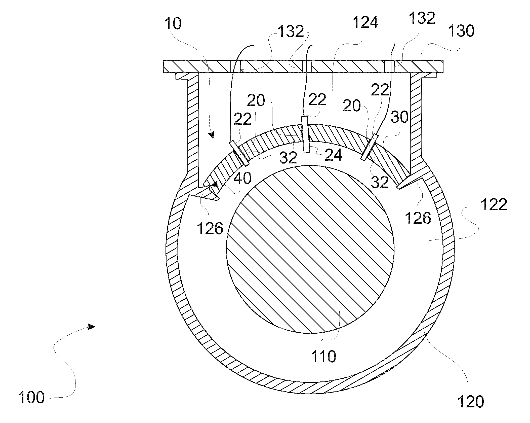
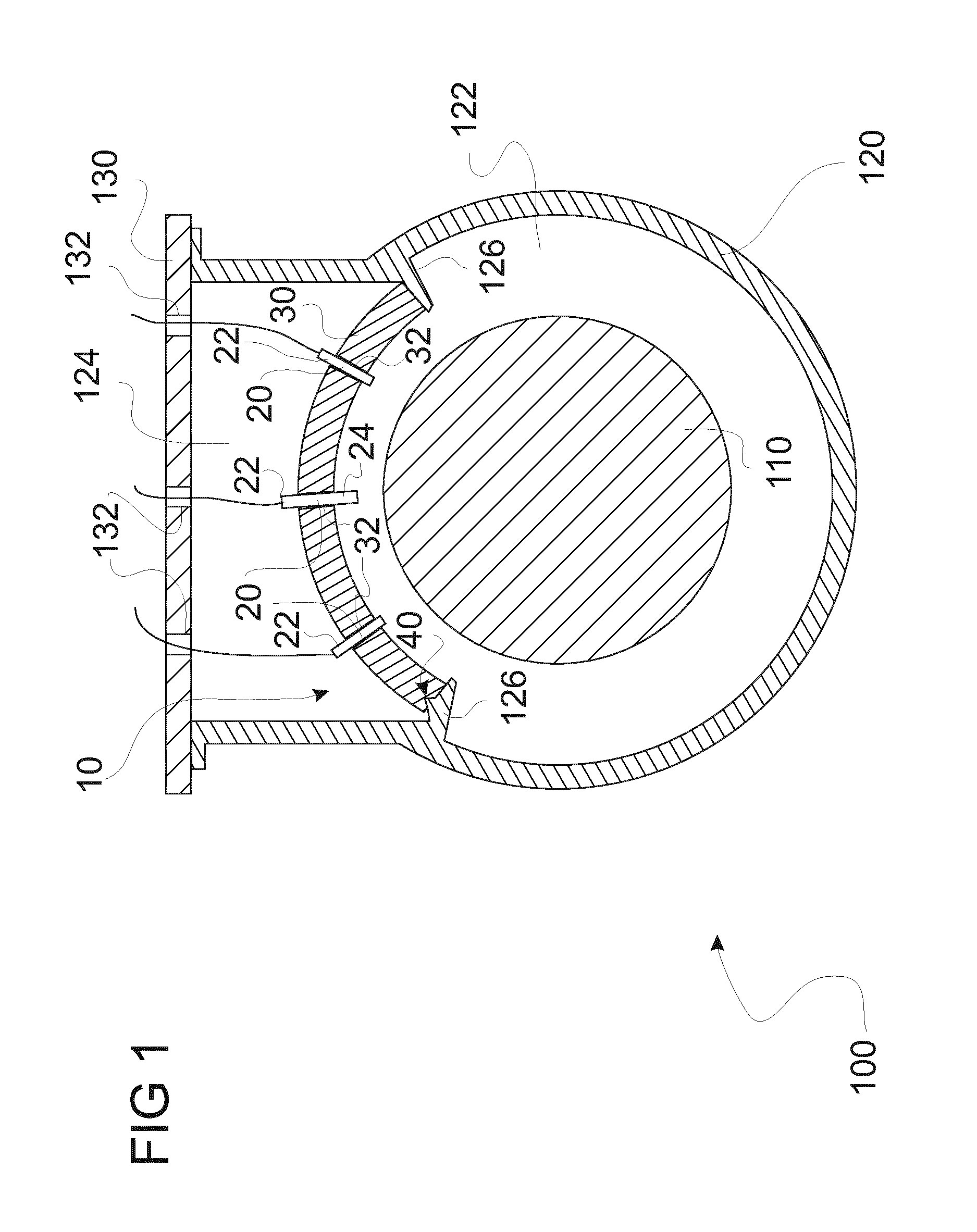
[0043]In FIG. 1, one embodiment of a machine, making use of a casing 120 and a detecting probe mounting device 10 is shown.

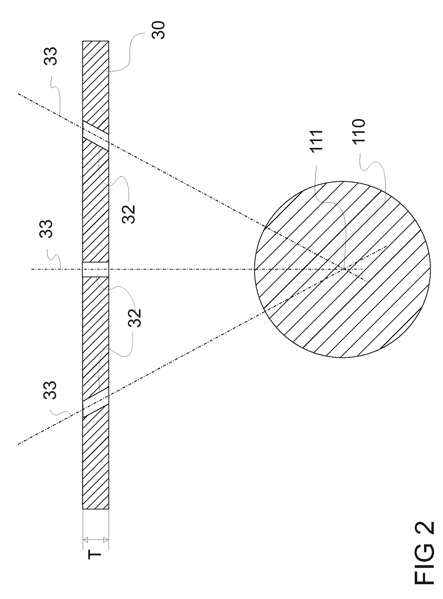
[0044]The detecting probe mounting device 10 of the embodiment of FIG. 1 comprises a curved, at least partly plate-like probe support structure 30. The curvature of the probe support structure 30 corresponds with the curvature of rotating member 110, which is a rotating shaft in the present embodiment. The correspondence between the two curvatures is to be understood such that the center of the curvature radius of the probe support structure 30 is identical or almost identical with the center of the rotating member 110.

[0045]Within the probe support structure 30, threaded through holes 32 are located. Detecting probes 20 are inserted in such through holes 32. The insertion took place such that the detecting probes 20 are orientated with their detecting part 24 facing the rotating member 110 and the connecting part 22 facing in the other, in particular contrary d...


PUM

PropertyMeasurementUnit
thicknessaaaaaaaaaa
curvatureaaaaaaaaaa
geometrical dimensionsaaaaaaaaaa

Abstract

A detecting probe mounting device for fixation in the proximity to a rotating member of a machine is provided. The detecting probe mounting device includes at least two detecting probes with a connecting part and a detecting part for detecting parameters of the machine and / or the rotating member, a probe support structure with one through hole for each detecting probe and with mounting means for mounting each detecting probe at the probe support structure, wherein in a mounted state the connecting part and the detecting part are located on different sides of each through hole, and fixing means for fixing the probe support structure at a predefined position in proximity to the rotating member of the machine, wherein in the fixed state the detecting part of each detecting probe is facing the rotating member.

Description

CROSS REFERENCE TO RELATED APPLICATIONS[0001]This application is the US National Stage of International Application No. PCT / EP2012 / 057485 filed Apr. 24, 2012, and claims the benefit thereof. The International Application claims the benefit of European Application No. EP 11166069.2 filed May 13, 2011. All of the applications are incorporated by reference herein in their entirety.FIELD OF INVENTION[0002]The present invention relates to a detecting probe mounting device, a casing for a machine with such a detecting probe mounting device as well as a respective machine and a method for servicing and / or replacing at least one detecting probe.BACKGROUND[0003]It is already known that machines comprising rotating members, like shafts or rotors or the like, are in need of detailed monitoring of the rotating member. In particular, the monitoring of the rotation speed or the vibration of the rotating member is necessary to make sure that the rotating member works in the predefined way and does...

Claims


Application Information

Patent Timeline
Patent Type & Authority Patents(United States)
IPC IPC(8): G01D11/24G01D11/30F16M11/04F16M13/02G01L19/14G01P1/02
CPCG01D11/30F16M11/041F16M13/02F16M2200/08
Inventor CARTER, DAVE
Owner SIEMENS ENERGY GLOBAL GMBH & CO KG
Why Eureka
Try Eureka