Safety coupling

a safety coupling and coupling technology, applied in the direction of couplings, rigid shaft couplings, mechanical devices, etc., can solve the problems of high cost, easy to determine, and unknown safety couplings that offer no visual inspection, etc., and achieve the effect of improving safety couplings

Active Publication Date: 2016-02-23
VOITH TURBO SAFESET
View PDF9 Cites 0 Cited by
  • Summary
  • Abstract
  • Description
  • Claims
  • Application Information

AI Technical Summary

Benefits of technology

[0029]The aim of the present invention is to provide an improved safety coupling which solves the above problems by resetting and utilizing the maximum arcuate distance for each operating cycle.

Problems solved by technology

The known safety coupling offers no visual inspection of, or easily ascertainable way of determining, the relative movement achieved between the coupling members at the start of each operating cycle.
These measures have proven to be extremely burdensome, especially in a situation where the safety coupling thus triggered, related to a drilling station, is located in an inaccessible place and position, such as high above a ground plane.

Method used


Image

  • Safety coupling
  • Safety coupling
  • Safety coupling

Examples


Embodiment Construction

[0059]It must first be observed that in the subsequent description of a currently proposed embodiment, which shows the significant characteristics associated with the invention and which will clarified by the figures shown in the following drawings, we have allowed for the selection of terms and specific terminology with the primary purpose of clarifying the invention idea.

[0060]However, it should be noted in this context that the expressions chosen here should not be seen as limiting only to the terms selected and utilized herein; but rather it is understood that each term so selected shall be construed to also include all technical equivalents which operate in the same or substantially the same manner, in order to thereby achieve the same or substantially the same intention and / or technical effect.

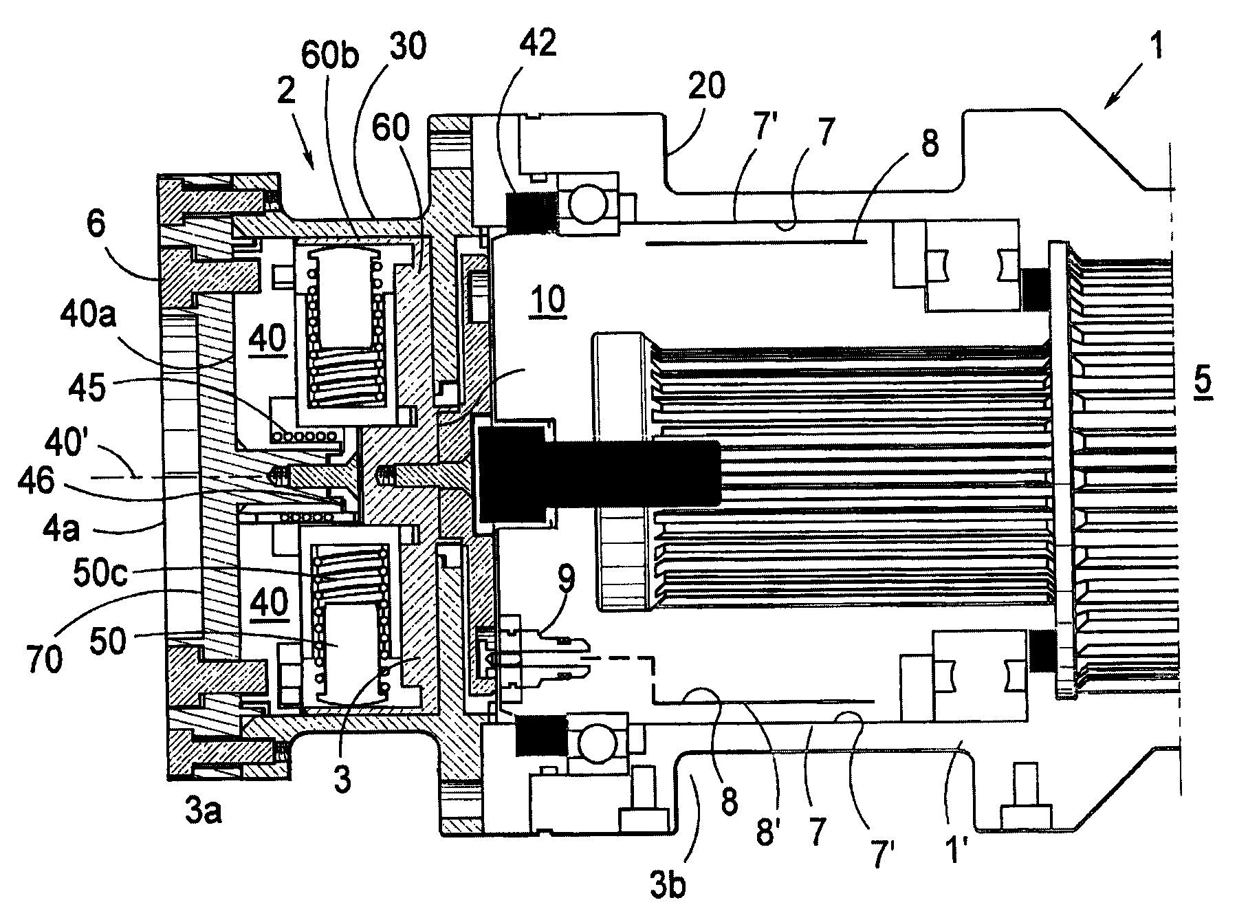
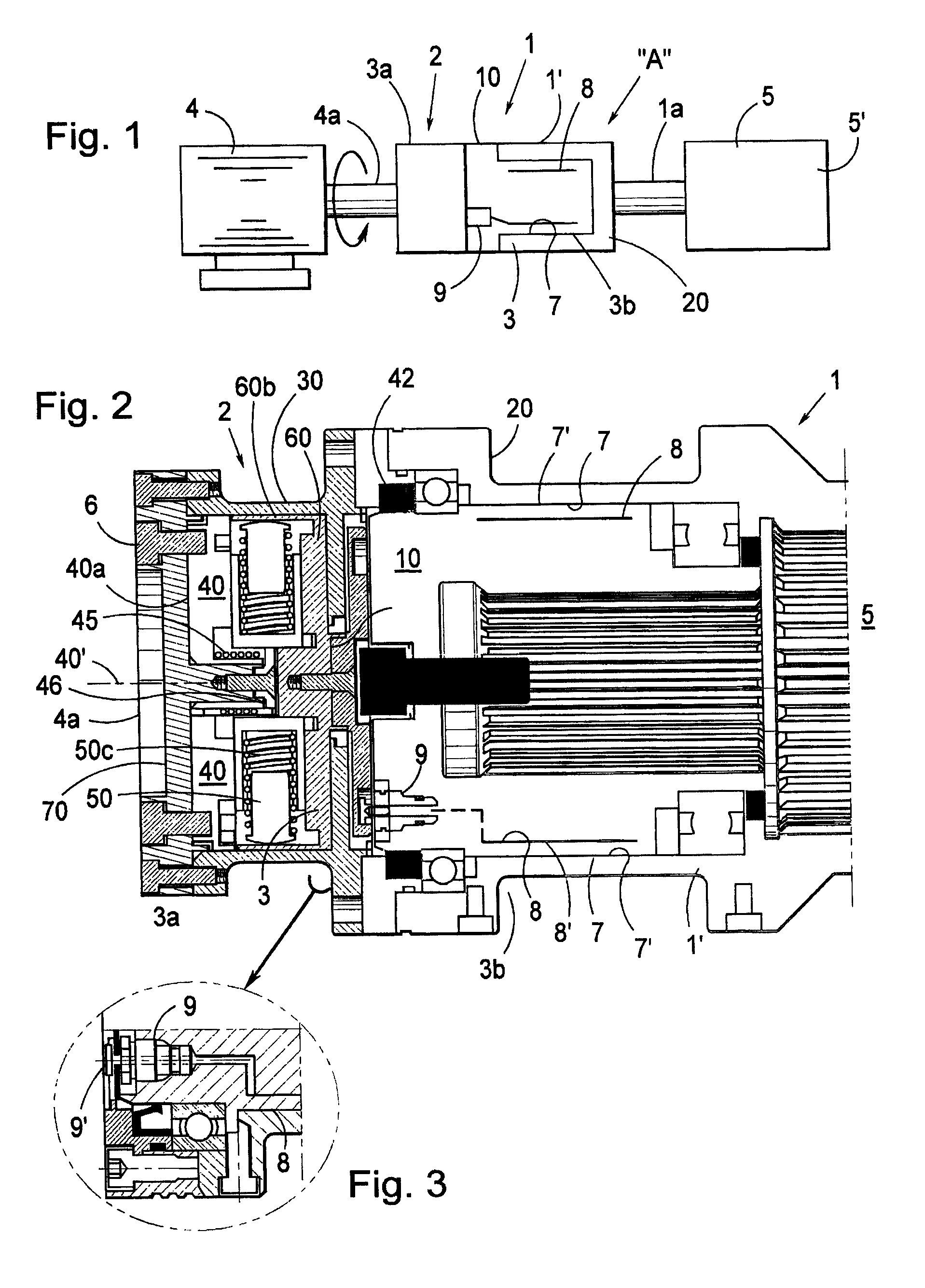
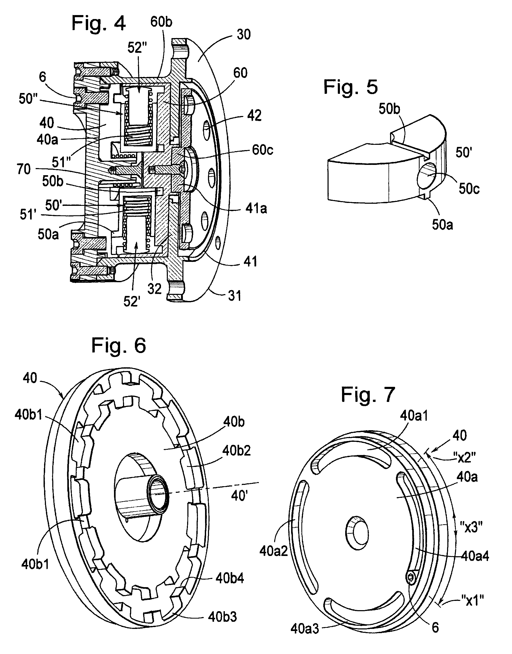
[0061]With reference to the accompanying FIGS. 1 to 14, not only the principles known in the art, but also for the present invention, are presented schematically and in detail, whereby t...


PUM


Abstract

The present invention comprises a safety mechanism (2, 3, 3a, 3b), which is related to and / or integrally formed with a safety coupling (1), wherein the safety coupling, with a related safety mechanism (3a) actuatable toward and into an initial active retaining position or toward and into a final inactive releasing position, is adapted, upon rotary motion, to allow for the transmission of torque between a first, driving coupling member (10) and a second, driven coupling member (20) and wherein said actuatable safety mechanism is adapted to be actuatable in a displacement from an initial active position, via a number of intermediate positions, to a final inactive position. The invention provides for the existence of a guided safety mechanism allocated to the safety coupling with means (40, 45), adapted, during a final operating cycle of the safety coupling, to allow the safety mechanism to be displaced in a direction toward and into the initial active position, and from there to again allow a limiting relative movement between the first and the second coupling members, during each subsequent operative cycle.

Description

CROSS-REFERENCE TO RELATED PATENT APPLICATIONS[0001]This application claims the benefit of International Application No. PCT / SE2012 / 050726, filed Jun. 27, 2012, which claims the benefit of Swedish Application No. 1100498-3, filed Jun. 27, 2011, both of which are incorporated herein by reference in their entirety.TECHNICAL FIELD OF THE INVENTION[0002]The present invention relates generally to a safety coupling. In the following description, the term “safety coupling” means a coordination between;[0003]a. a safety arrangement coordinated or integrated with a coupling unit.[0004]b. a safety arrangement for a safety mechanism which can be actuated to an “active” or “inactive” position, the safety mechanism being integrally formed with or forming a separate unit from the safety arrangement, and[0005]c. a torque-transmitting coupling unit with one driving coupling member and one driven coupling member and equipped with overload protection in the form of the safety arrangement described in...

Claims


Application Information

Patent Timeline
Patent Type & Authority Patents(United States)
IPC IPC(8): F16D13/12F16D1/08F16D3/02F16D9/06F16D43/28
CPCF16D1/0805F16D3/02F16D9/06F16D43/28F16D7/021F16D9/10F16D13/12
Inventor FALK, CURT GUNNARJACOBS, MIKAEL
Owner VOITH TURBO SAFESET
Why Eureka
Try Eureka