System for anticipating required navigation performance

a technology of navigation performance and system, applied in the field of flight management systems, can solve the problems of inertial drift and the inability of pilots to access the accuracy level required with respect to the current accuracy level, and achieve the effect of simple, accurate and easy to access

Active Publication Date: 2016-03-01
THALES SA
View PDF4 Cites 0 Cited by
  • Summary
  • Abstract
  • Description
  • Claims
  • Application Information

AI Technical Summary

Benefits of technology

[0028]An aim of the invention is to give the pilot a simple, accurate and easily accessible means for knowing the demands required by the RNP procedure for the current and future trajectory portions.
[0029]According to one aspect of the invention, there is proposed an onboard flight management system in an aircraft comprising means for continuously calculating first geolocation data, from data received by at least one external geolocation device, comprising a current position and future positions of an aircraft along a trajectory sequenced in several portions and comprising second data comprising demands required by an international procedure called “Required Navigation Performance”, or RNP, for each of the portions of the trajectory. The said management system comprises a means for displaying first and second data all the way along the trajectory, the first and second data being represented graphically and simultaneously on the said display means in order to enable the pilot to anticipate the flight characteristics for the aircraft and make them converge toward the required demands of the next trajectory portion.
[0030]The pilot will thus be able to anticipate at the earliest moment changes in the required accuracy level.

Problems solved by technology

As regards inertial means, they suffer from the problem of inertial drift inherent to these systems.
Presently, the accuracy level required with respect to the current accuracy level is not easily accessible by the pilot.

Method used


Image

  • System for anticipating required navigation performance
  • System for anticipating required navigation performance
  • System for anticipating required navigation performance

Examples


Embodiment Construction

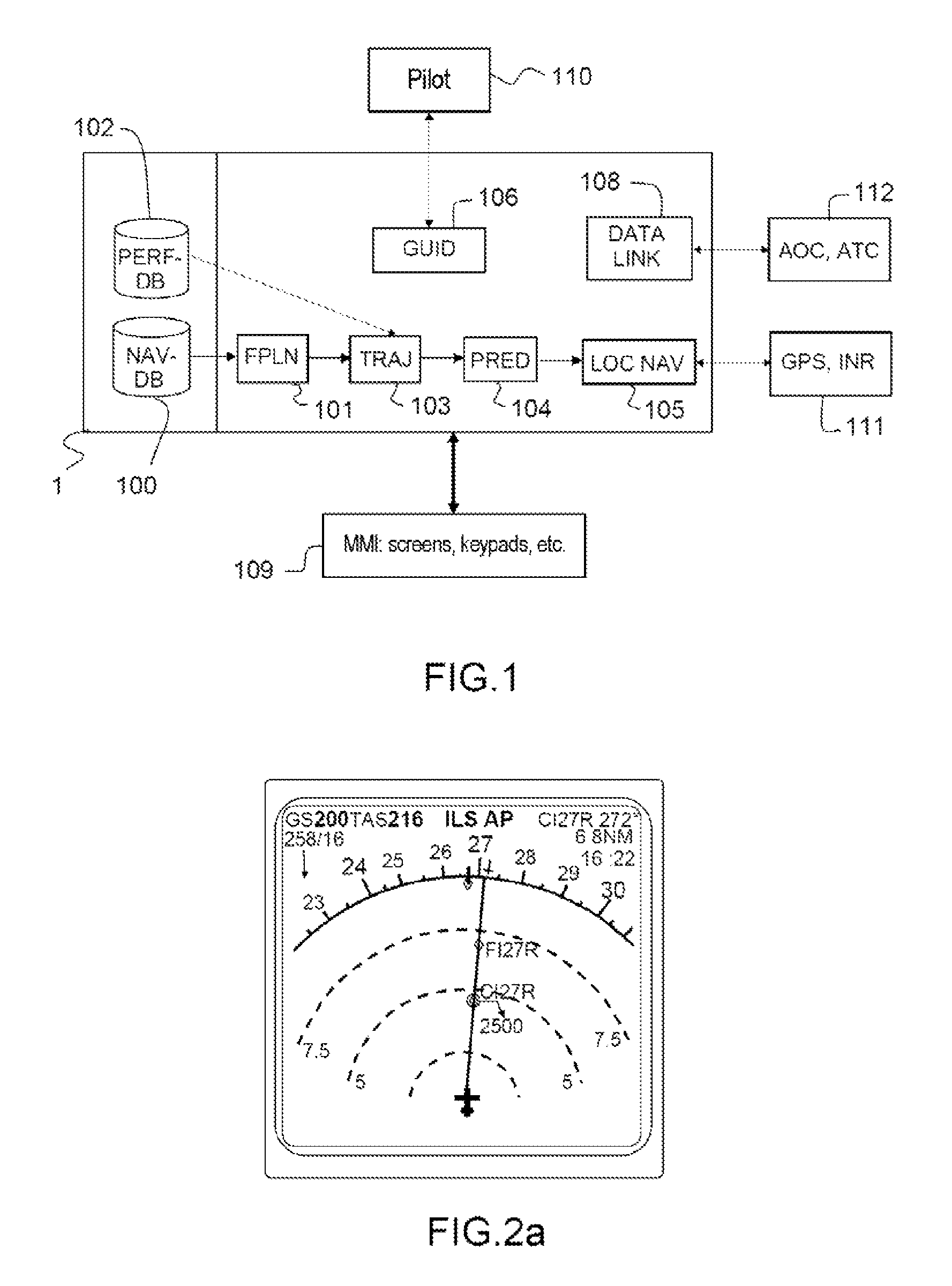
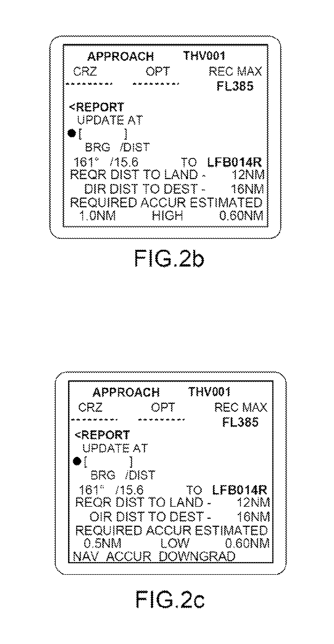
[0040]FIGS. 2a, 2b and 2c represent a user interface 109 such as a navigation screen of a flight management system.

[0041]FIG. 2a represents a first page of a navigation screen of the flight management system on board an aircraft. This first page indicates the trajectory to be followed by the aircraft. This page is generally easily accessible by the pilot of the aircraft and does not require any maneuver on the part of the pilot to have access to it; this page is accessible by the pilot 110 in the “head-up” position.

[0042]The current position of the aircraft is indicated by a symbol in the shape of an aircraft; it is represented at the center of three concentric circles of increasing radius. The trajectory of the aircraft is indicated by an axis passing through the current position of the aircraft, and a first and a second waypoint. The current position and the first waypoint define a first current trajectory portion, a trajectory portion being commonly referred to as a “leg”. The fi...


PUM


Abstract

An onboard flight management system in an aircraft comprises means for continuously calculating first geolocation data, from data received from at least one external geolocation device, comprising a current position and future positions of an aircraft along a trajectory sequenced in several portions and comprising second data comprising demands required by an international navigation procedure called “Required Navigation Performance”, or RNP, for all the portions of the trajectory. The management system additionally comprises a means for displaying first and second data all the way along the trajectory, the first and second data being represented graphically and simultaneously on the said display means in order to enable the pilot to anticipate the flight characteristics for the aircraft and make them converge toward the required demands of the next trajectory portion.

Description

CROSS-REFERENCE TO RELATED APPLICATIONS[0001]This application claims priority to foreign French patent application No. FR 1203011, filed on Nov. 9, 2012.FIELD OF THE INVENTION[0002]The invention is placed in the field of flight management systems and more particularly trajectory calculation means.BACKGROUND[0003]A Flight Management System, or FMS, is an onboard device on an aircraft. It provides for working out a flight plan on board and its modification in the event, notably, of rerouting. A flight plan is the detailed description of the route to be followed by an aircraft within the framework of a planned flight. It includes notably a chronological sequence of waypoints described by their position, their altitude and their time of overflight. A set of waypoints and the segments connecting them form the reference trajectory to be followed by the aircraft with a view to best adhering to its flight plan. This trajectory is a valuable aid both to the ground control personnel and to th...

Claims


Application Information

Patent Timeline
Patent Type & Authority Patents(United States)
IPC IPC(8): G01C21/00B64C19/00G05D1/10
CPCB64C19/00G01C21/00G05D1/101
Inventor BALOCHE, NORBERTBARNETCHE, BERTRANDROGER, MICHEL
Owner THALES SA
Why Eureka
Try Eureka