
Process for finding a path in an automated handling system, and handling system with corresponding control module for finding a path

a technology of automatic handling system and path finding, which is applied in the direction of electric programme control, program control, instruments, etc., can solve the problems of difficult and complex comparison of different collision procedures with each other, the teaching process soon reaches its limits, and the complexity of such systems to define single courses of movements. achieve the effect of rapid and reliable results

Active Publication Date: 2016-03-08
TECAN TRADING AG
View PDF2 Cites 6 Cited by
  • Summary
  • Abstract
  • Description
  • Claims
  • Application Information

AI Technical Summary

Benefits of technology

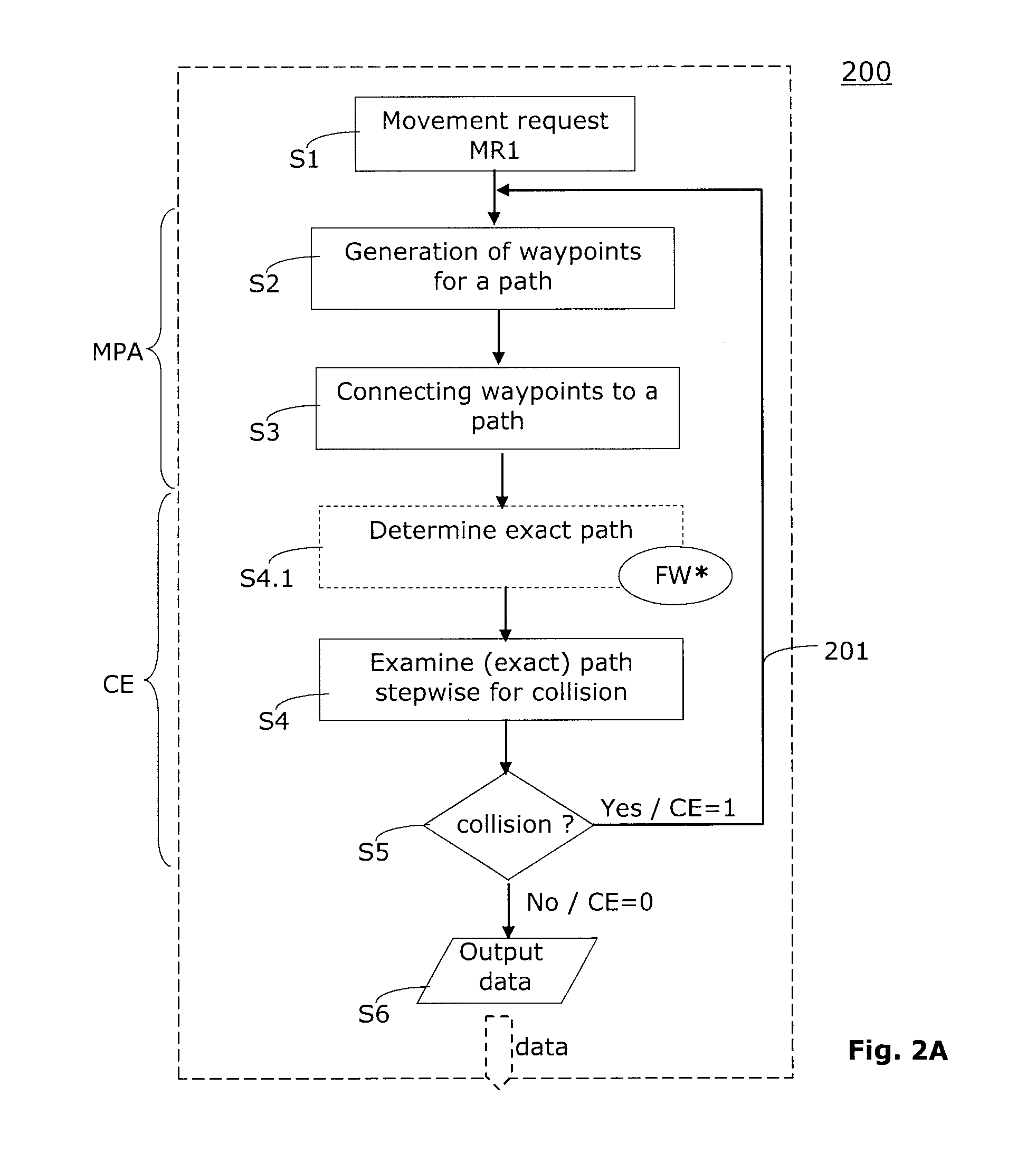
[0036]A particular advantage of the invention is based on unraveling into a quasi-static collision examination and a dynamic collision examination, as this unraveling provides rapid and reliable results.
is based on unraveling into a quasi-static collision examination and a dynamic collision examination, as this unraveling provides rapid and reliable results.

Problems solved by technology

It may be very complex in such systems to define the single courses of movements in such a way that no collision or mutual impairments occurs.
However, such a teach-in process soon reaches its limits e.g. when an entire process shall be optimized.
In the end, it may be concluded from the theoretical observations that it is very difficult and complex to compare the different collision procedures with each other.
Thus, there is the problem to configure the controller of a multi-axial handling system as flexible and productive as possible, wherein a collision avoidance for single, moving arms of such a handling system shall be carried out as fast as possible.

Method used


Image

  • Process for finding a path in an automated handling system, and handling system with corresponding control module for finding a path
  • Process for finding a path in an automated handling system, and handling system with corresponding control module for finding a path
  • Process for finding a path in an automated handling system, and handling system with corresponding control module for finding a path

Examples


Embodiment Construction

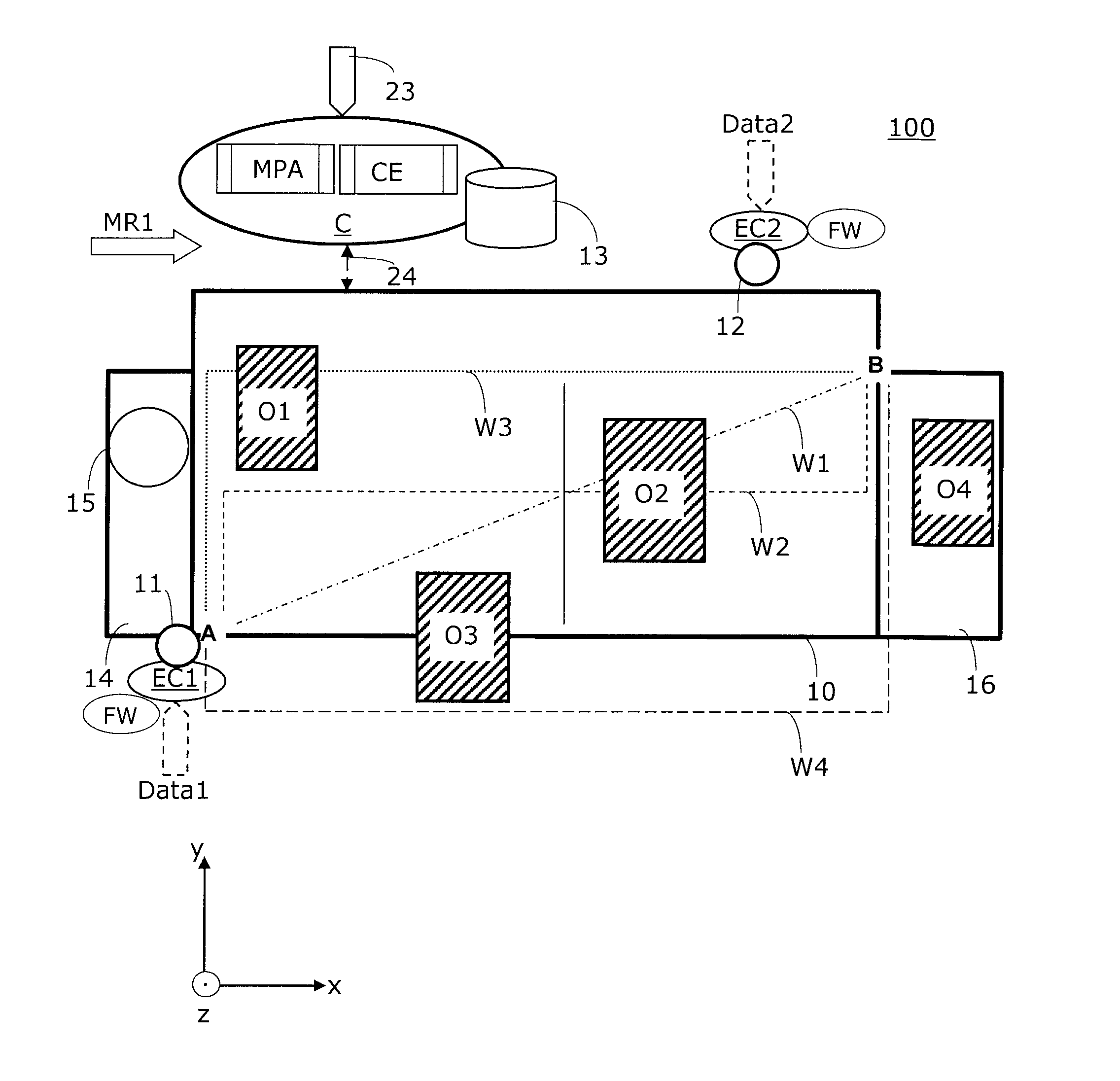
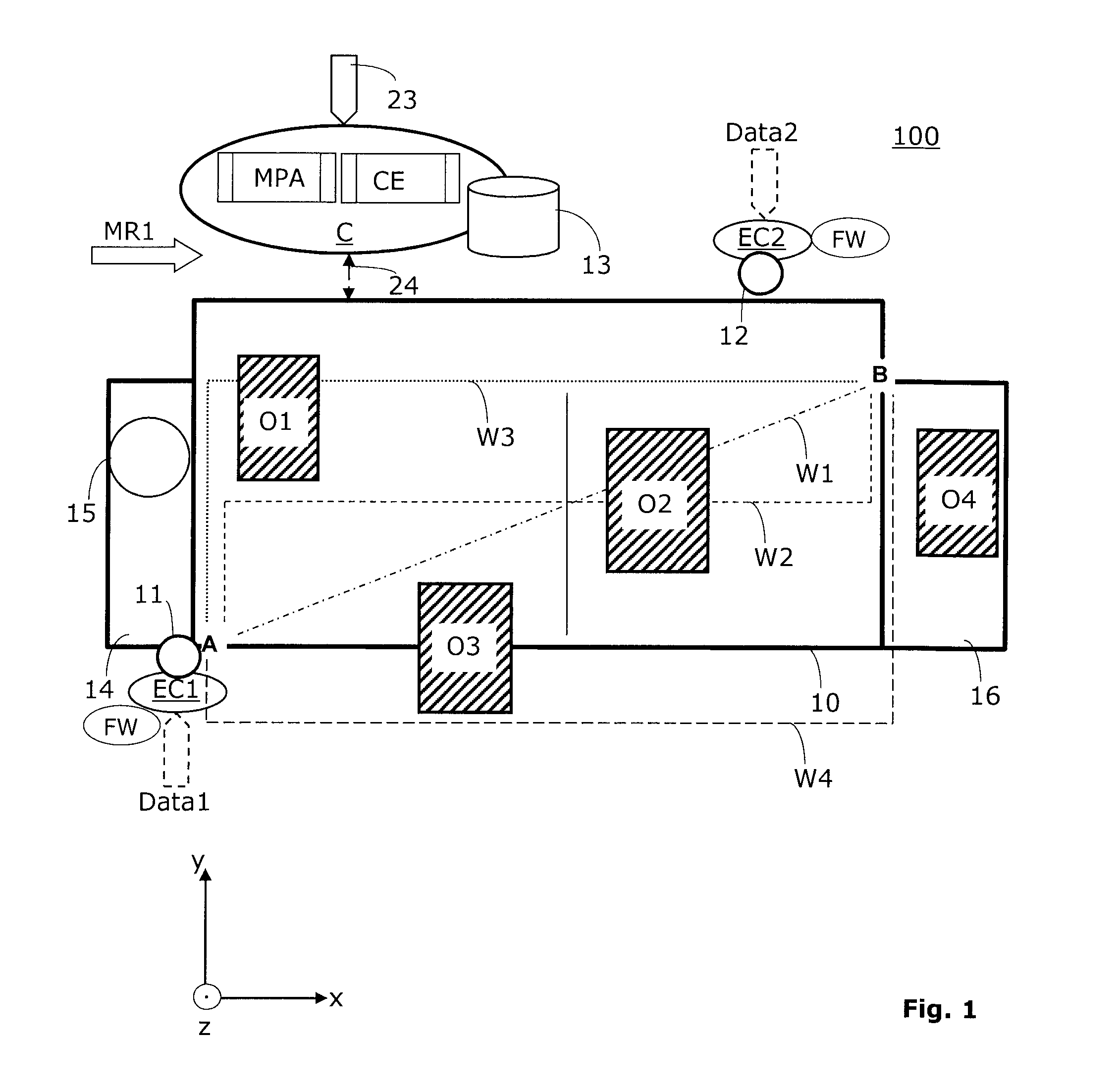
[0049]In the following, liquid handling systems 100 will be described by way of example, whereby the invention may be applied without problems also to other handling systems 100. The handling systems 100 are denominated in the following in short as systems 100.

[0050]The FIG. 1 shows a system 100 which here comprises a working area 10 being arranged essentially horizontally and configured for quasi-statically placing at least one (liquid) container O1. In FIG. 1 a situation is shown in which in total four container O1-O4 or other objects are arranged on the working area 10. The system 100 further comprises at least two numerically controlled (handling) arms 11, 12, which are here depicted as simple circles. These two arms 11, 12 are movable over the working area 10. For this purpose each of the two arms 11, 12 has an own drive system, so that both arms 11, 12 are movable spatially and temporally independent from each other.

[0051]In FIG. 1 and the other Figures, the driving systems ar...


PUM

PropertyMeasurementUnit
timeaaaaaaaaaa
movementaaaaaaaaaa
timeaaaaaaaaaa

Abstract

An Automated handling system has a working area, at least one object in the working area, at least a first numerically controlled arm and at least a second numerically controlled arm. The arms are movable above the working area and have a collision avoidance mechanism. The current actual topography of the working area is determinable, a movement planning algorithm determines a path from a first position to a second position, wherein in the first application of the movement planning algorithm a reference path, a quasi-static collision examination for the path, which has been provided by the movement planning algorithm, is applicable, a dynamic collision examination for the path, which has been suggested by the movement planning algorithm, is applicable, and wherein the collision examination determine whether, when moving the first arm a collision would be provoked.

Description

RELATED PATENT APPLICATIONS[0001]This patent application claims priority of the Swiss patent application No. 00350 / 14, filed on Mar. 10, 2014. The whole content of this priority application is herein incorporated in its entirety by reference.RELATED FIELD OF TECHNOLOGY[0002]The invention relates to processes for finding a path in an automated handling system as well as to handling systems having a corresponding control module for finding a path. In particular, the invention relates to the path finding in computer-controlled liquid handling systems.BACKGROUND OF THE INVENTION[0003]There are several medical, biological, chemical and pharmaceutical devices which are concerned with the handling and use of liquids. For example, there are automated liquid handling systems for carrying out medical, biological, physical and chemical investigations or to carry out processes in these areas.[0004]Today, most of the automated liquid handling systems are so called computer-controlled handling sy...

Claims


Application Information

Patent Timeline
Patent Type & Authority Patents(United States)
IPC IPC(8): G05B19/18G05B19/4061B25J9/16G01N35/00B25J9/00G01N35/10G01N35/04
CPCB25J9/1676B25J9/0087B25J9/1666G01N35/0099G05B19/4061G01N35/10G01N2035/0491G05B2219/39083G05B2219/40497Y10S901/14Y10S901/49B25J9/026
Inventor BRANDENBERGER, JOEL
Owner TECAN TRADING AG
Learn More