
Diagnostic device for analyte detection

Inactive Publication Date: 2007-08-14
NEXUS DX
View PDF17 Cites 28 Cited by
  • Summary
  • Abstract
  • Description
  • Claims
  • Application Information

AI Technical Summary

Benefits of technology

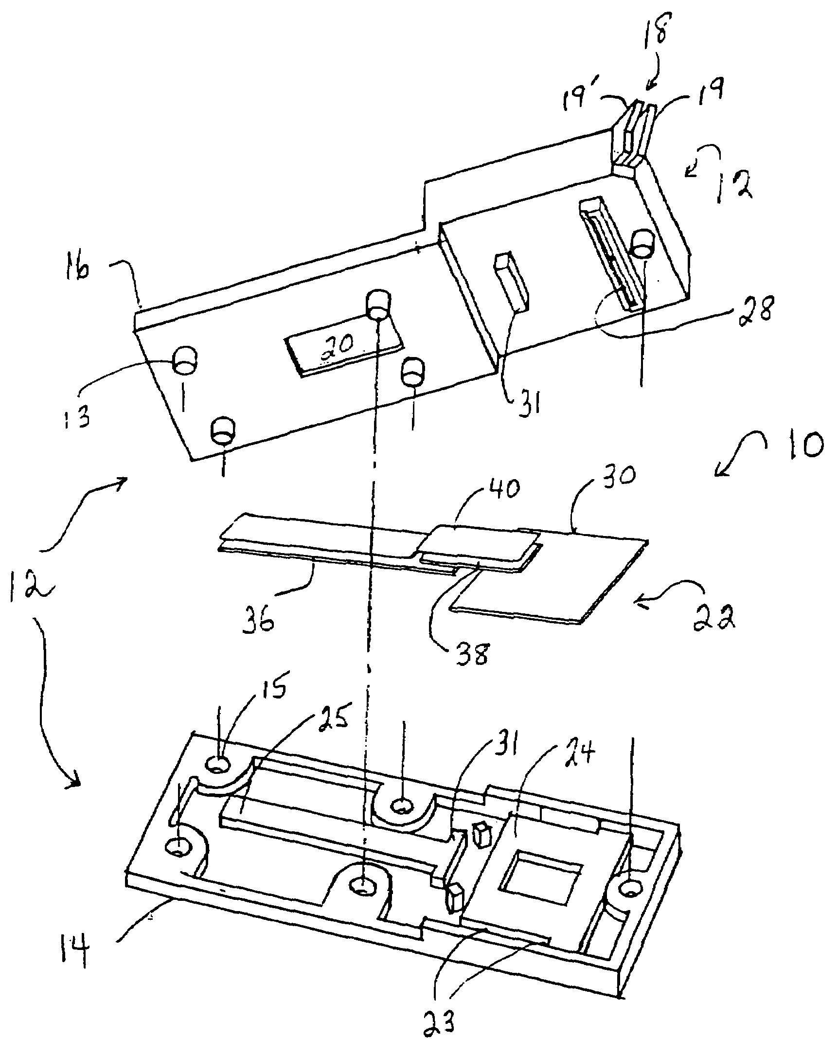
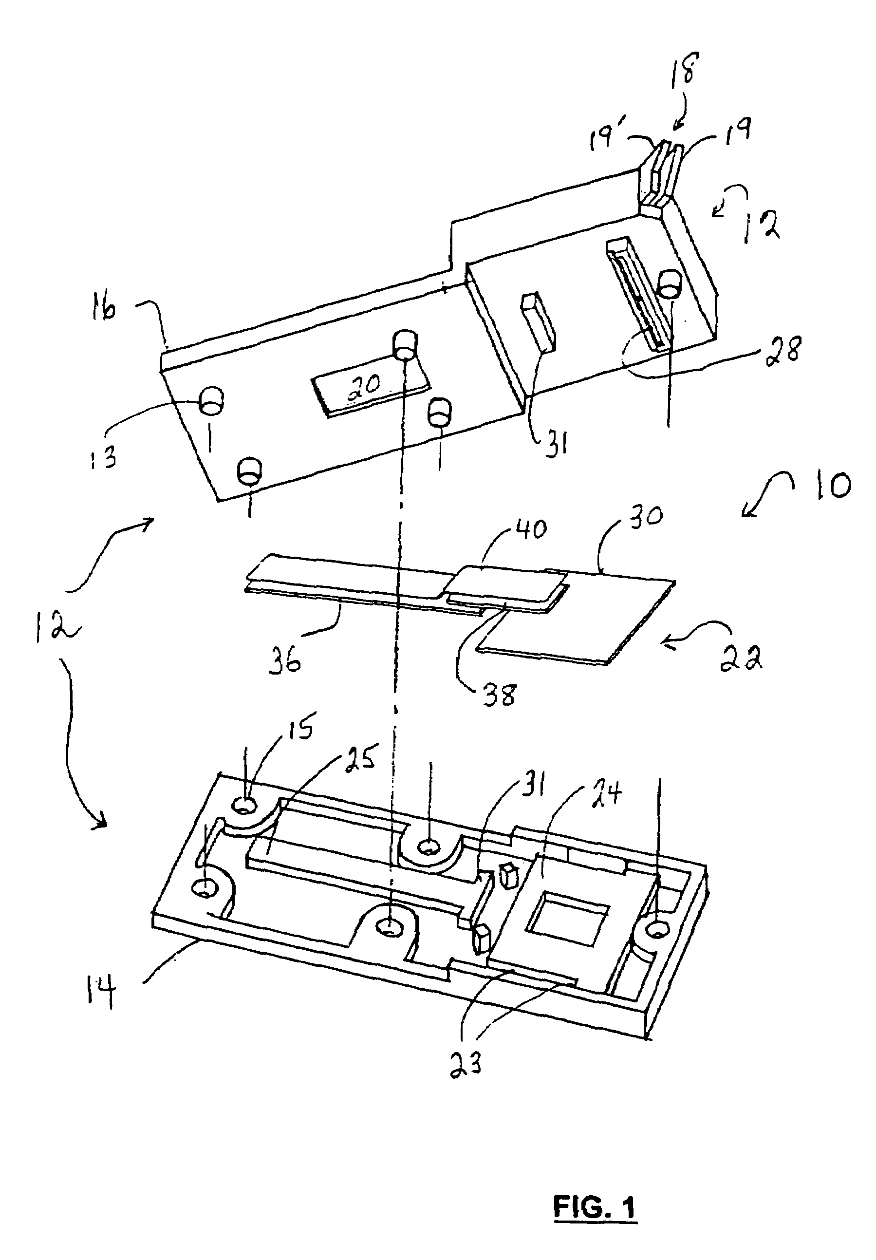
[0009]The present invention provides a device of the type useful to perform an in vitro immunodiagnostic assay for an analyte of interest. The present device can be used particularly, but not exclusively, to detect the presence of cardiac analytes in a sample of whole blood, serum or plasma, including for instance troponin I, C and / or T, myoglobin, myosin light chain, creatine kinase M and / or B, and the like. The device is adapted to be hand-held, and to provide rapid and reliable results using sample volumes as small as the blood volume generated from a single finger prick. In addition to its versatility and convenience, the present device is engineered and designed for production at low cost and with minimum labour and waste, relative to devices with similar high performance and diagnostic accuracy.
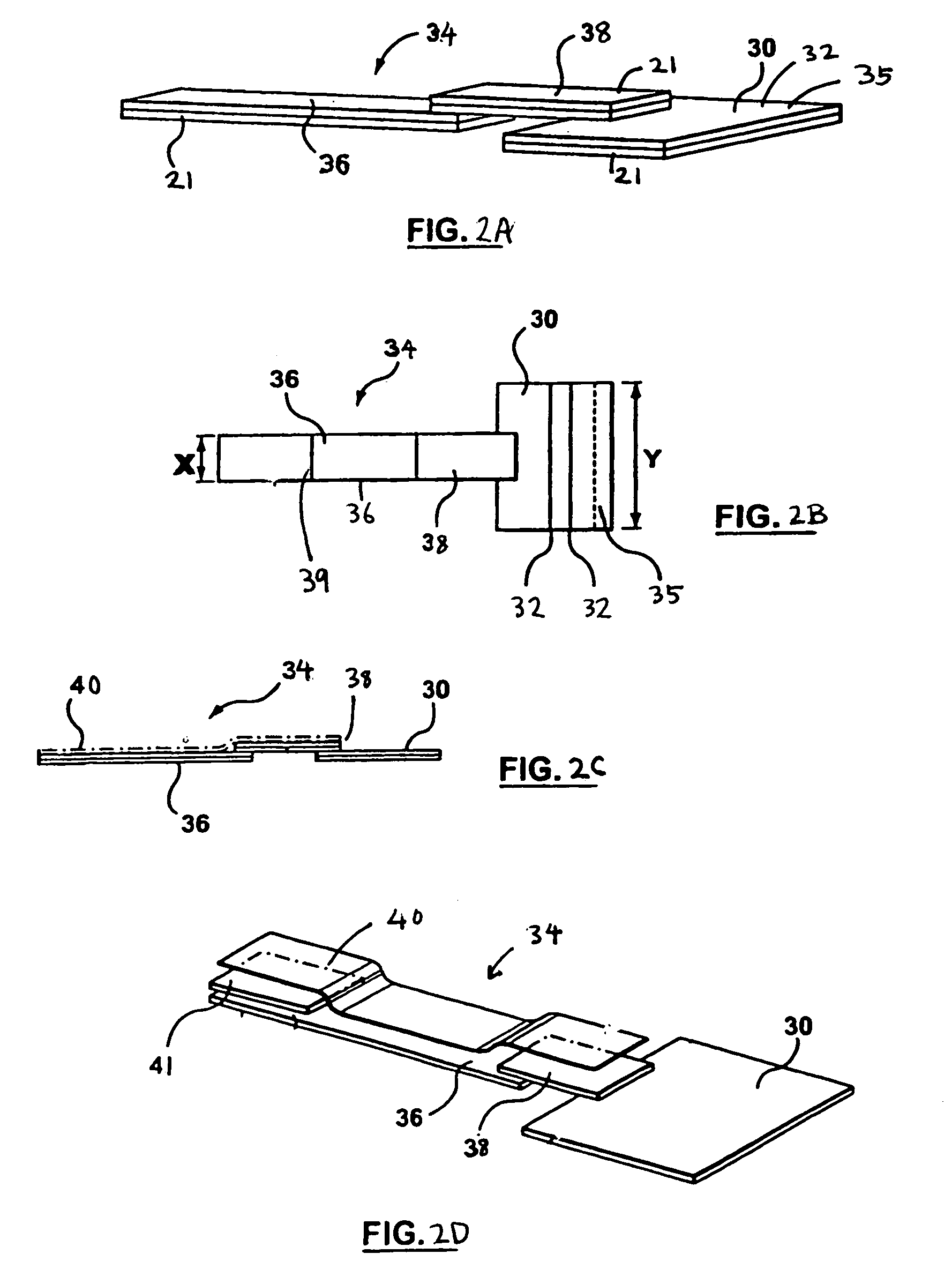
[0010]The present device utilizes a carrier that is adapted for highly efficient sample flow, which not only maximizes use of sample volume but also maximizes analyte flow across the analyte capture line. In one embodiment of the present device, this is achieved using a carrier formed of an array of pads, including a sample pad for receiving sample, and at least one detection pad which defines a detection channel having a width that is narrower than the sample pad. In a preferred embodiment, the detection channel comprises both a detection pad and a bridging pad that is coupled in flow communication between the sample pad and the detection pad. In a preferred embodiment, the bridging pad has a lower surface that is in contact with the upper surfaces of the sample pad and the detection pad. By this arrangement, there is provided an interface that functions to filter certain particulates from the sample migrating across the carrier pad array. In a further preferred embodiment, the bridging pad and the detection pad are coupled using an upper barrier layer that is impervious to liquid. By this arrangement, capillary flow is enhanced for all sample migrating into the detection channel, thereby increasing and concentrating the flow of sample, and analyte, across the detection pad.
[0011]By providing a carrier that is modular in design and comprises individual pads, the present device can be produced with far less waste of carrier material than a single carrier sheet that performs similarly, to channel sample into a narrow detection channel. Moreover, the rate and volume of sample flow across the detection pad is increased, relative to a single sheet design, by using the overlapping pad arrangement and barrier layer by which the various pads are coupled in flow communication.
[0012]Also in the present device, there are provided certain key features that simplify manufacturing and handling of the device during use and transportation. The present device comprises a housing and a carrier material having a surface suitable for conducting the assay, which in one embodiment is constituted by the pad array just described. In the present device, the housing is provided with a sample inlet that communicates with the carrier by way of a sample deposition channel. In the present device, the sample deposition channel is adapted to deposit sample as a generally linear band having its longer axis generally transverse to the path of sample flow on the carrier. Desirably, the width of the sample band deposited from the deposition channel is greater than the width of the detection channel through which the deposited sample migrates. As distinct from sample deposition channels that are U-shaped, the present linear deposition channel offers greater ease of manufacture. Moreover, it has been found that the U-shaped design, intended to channel sample for confocal flow toward a narrow detection channel is unnecessary; sample deposited from a linear band that is perpendicular to sample flow and wider than the downstream detection channel, as in the present invention, has been found to migrate naturally toward and into the detection channel without significant loss of sample to regions of flow stagnation. Moreover, by this arrangement, reagent-bound analyte becomes concentrated at the entry to the detection channel, and thus migrates across the detection pad in concentrated form to enhance assay sensitivity.

Problems solved by technology

Importantly, however, the engineering required to perform the test in a rapid and reproducible fashion, with maximum sensitivity and specificity and with minimum sample volume, is highly demanding.

Method used


Image

  • Diagnostic device for analyte detection
  • Diagnostic device for analyte detection
  • Diagnostic device for analyte detection

Examples


example 1

[0052]The converging pattern of sample flow toward the detection channel was first confirmed, in an experiment in which normal human serum was delivered as a linear band from the deposition channel and then permitted to flow for about ten minutes toward the detection channel. The bridge was then removed, thereby stopping sample flow within the sample pad, to reveal the label flow pattern. As illustrated in FIG. 7A, the labeled detector antibodies entrained within the migrating sample clearly displayed flow converging toward the bridging pad of the detection zone. This same converging sample flow is seen in assays that run to completion without bridging pad interruption. Notwithstanding the reduced width of the detection channel relative to the span of labeled detector antibody deposited on the sample pad, there was very little detectable stagnation of reagent or sample in the shoulders of the sample pad. Substantially all of the sample and reagent migrated toward the bridge leading ...

example 2

[0053]The carrier pad arrangement just described was also employed in the present device for the detection of rCKMB, as analyte. In this assay, 50 μl of normal human serum alone or spiked with rCKMB was tested. The results at 15 min are illustrated in FIGS. 7B (normal human serum), 7C (normal human serum spiked with 6.25 ng / ml rCKMB), and 7D (spiked with 32.35 ng / ml rCKMB). These Figures reveal that label deposited on the sample pad flowed almost completely out of the sample pad and into the detection zone, there being very marginal and negligible stagnation of labeled reagents in the sample pad shoulders. The results also reveal that rCKMB is detected in the spiked samples, the assay being more sensitive to detection of CKMB at the higher concentrations.

example 3

[0054]The device also was assessed for its ability to retard the flow of red blood cells, so that they do not migrate into and obscured results otherwise visible at the capture line. To this end, 50 μl of fresh heparinized human whole blood was tested. After 15 min, the majority of the red blood cells were retained in the sample pad, and the front of the red blood cells was restricted at the center of the bridging pad. After about 1 hour, the front of the red blood cells was stabilized at just beyond the bridge before reaching the capture line within the read-out window, and remained there afterwards. Hemolysis was not visually detectable. The result at 72 hours is shown in FIG. 7E. It will thus be appreciated that the bridging pad and its elevation relative to the sample and detection pads also contributes to the filtration of sample particulates including red blood cells, and that this carrier pad array is particularly well adapted for detection of soluble analytes present in bloo...


PUM


Abstract

The present invention provides a hand-held device of the type useful to perform an in vitro immunodiagnostic assay for an analyte of interest. In embodiments of the invention, the device incorporates a carrier for conducting the assay which comprises an array of pads including a sample pad, a narrow detection pad for detecting analyte, and a bridging pad coupled in flow communication therebetween. The device is provided with a housing adapted to deliver sample onto the carrier as a linear band having a width greater than the detection pad. In combination, these features yield a device that retains the sensitivity required for diagnostic accuracy, yet is improved in terms of cost and ease of manufacture.

Description

FIELD OF THE INVENTION[0001]This invention relates to the detection of analytes including those that are relevant in medical diagnosis. More particularly, the invention relates to devices that typically are hand-held and allow for the detection of analytes in specimens such as body fluids, environmental samples and the like.BACKGROUND OF THE INVENTION[0002]A wide variety of devices are now available for detecting analytes present in body fluids, such as whole blood, plasma, serum and urine, to aid in medical diagnosis. The simplest form of such a device performs the in vitro diagnostic test on the surface of a dry porous carrier, such as a sheet or strip of nitrocellulose membrane, which is usually contained within a housing that defines a sample application site and a detection site for viewing the assay result. In the so-called “spot test”, sample is applied as a drop to a carrier having immobilized thereon a reagent capable of binding to the analyte targeted for detection. After ...

Claims


Application Information

Patent Timeline
IPC IPC(8): G01N33/53G01N33/543G01N33/558
CPCG01N33/54386G01N33/558G01N33/54388
Inventor HU, WEI
Owner NEXUS DX
Learn More