

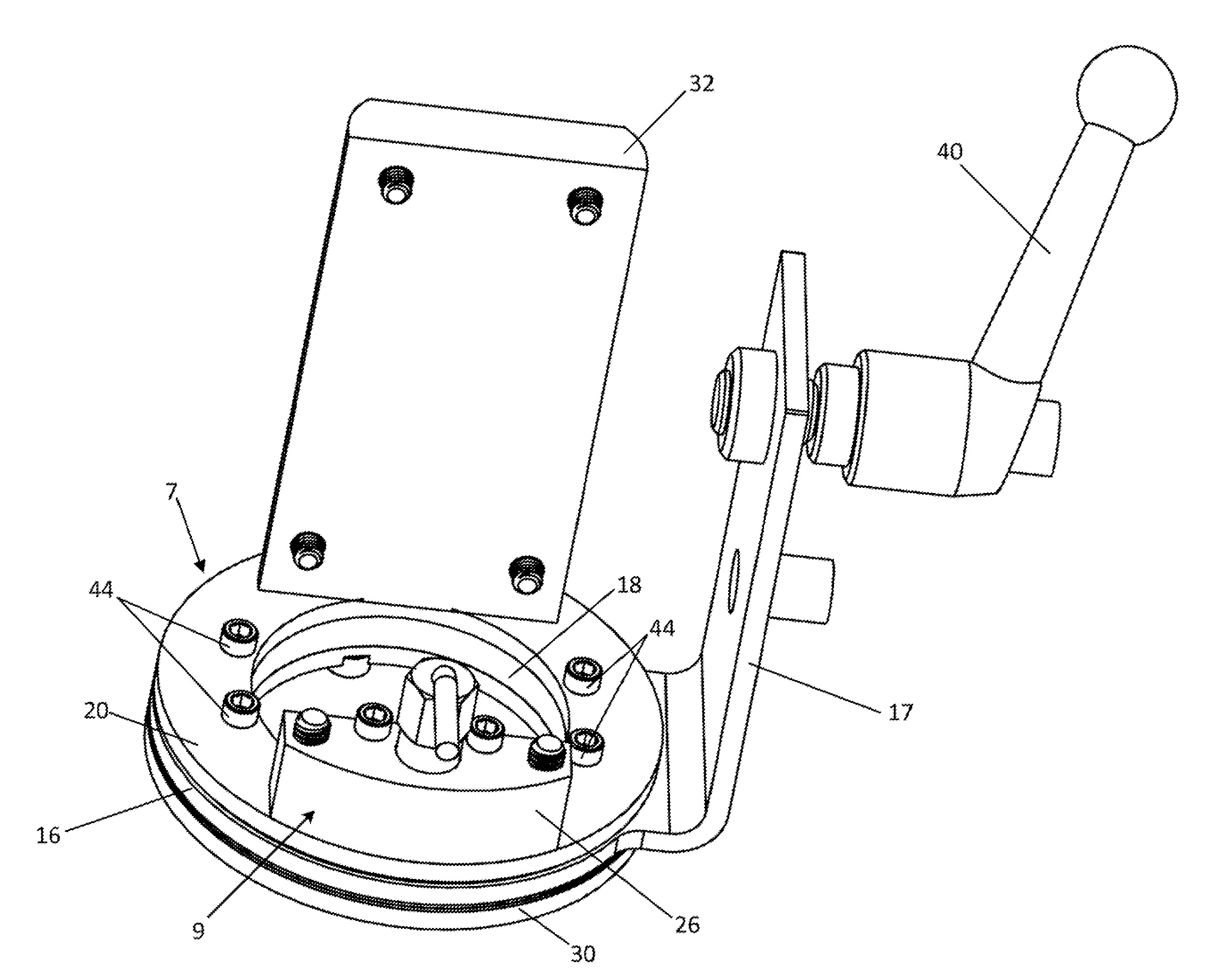
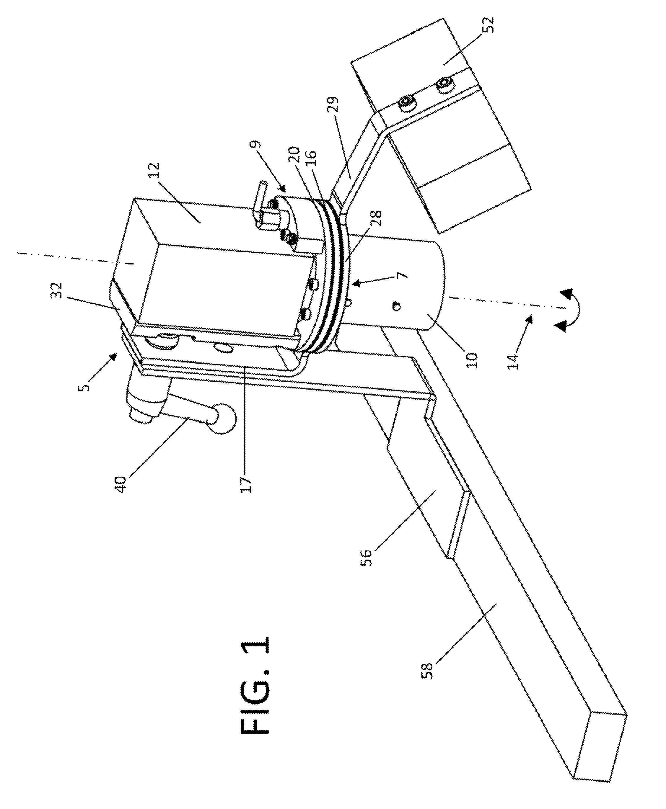
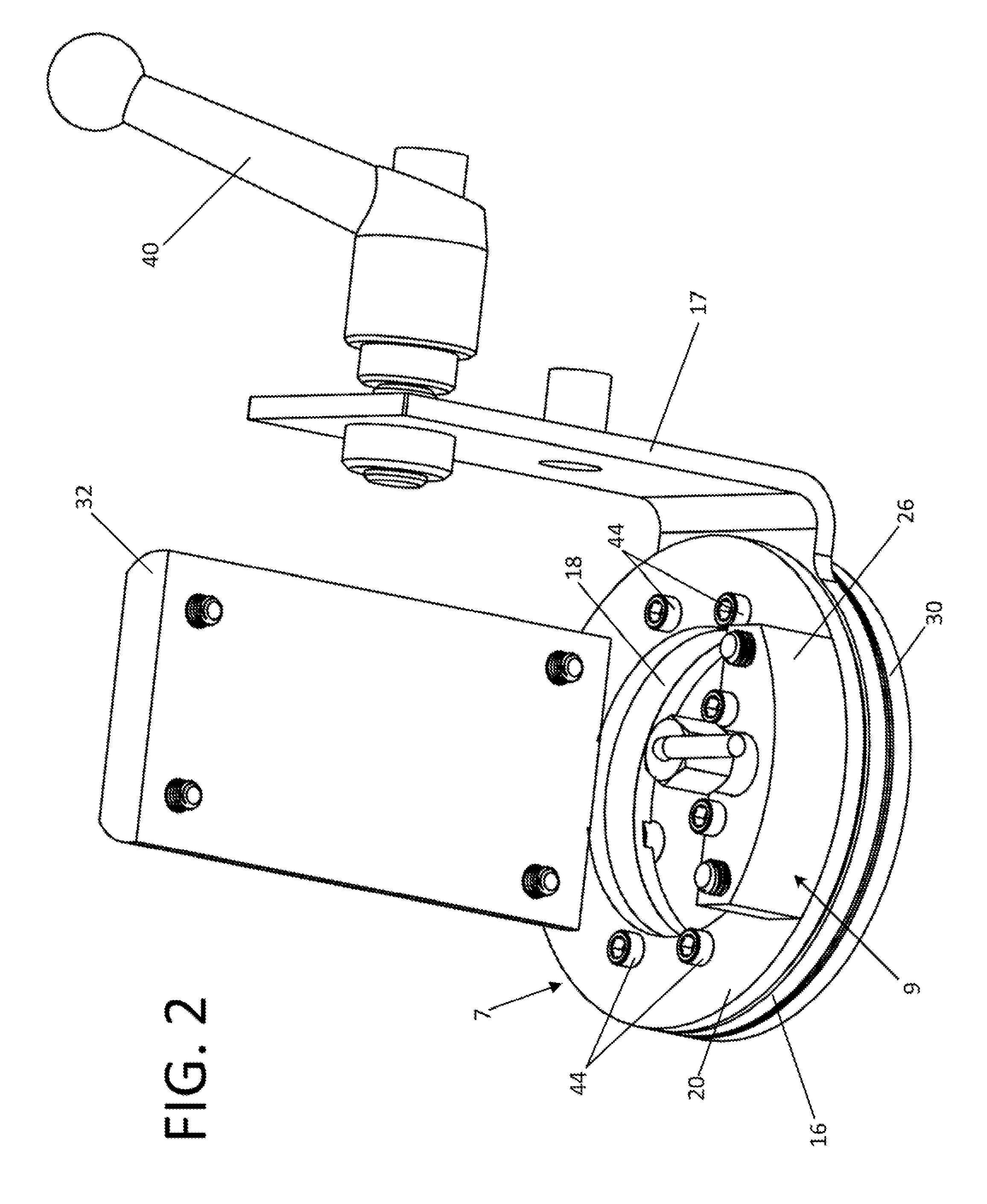
Machine vision camera mount with rotational adjustment
a camera mount and rotation adjustment technology, applied in the field of camera mounts and brackets, can solve the problems that none of the disclosures provided in these references is suitable for rapid and repeatable positional, and achieve the effect of reducing the overall size of the device, optics, camera and lighting
- Summary
- Abstract
- Description
- Claims
- Application Information
AI Technical Summary
Benefits of technology
Problems solved by technology
Method used
Image

Examples
Embodiment Construction
[0022]This disclosure is not limited to the particular systems, devices and methods described, as these may vary. The terminology used in the description is for the purpose of describing the particular versions or embodiments only, and is not intended to limit the scope.
[0023]As used in this document, the singular forms “a,”“an,” and “the” include plural references unless the context clearly dictates otherwise. Unless defined otherwise, all technical and scientific terms used herein have the same meanings as commonly understood by one of ordinary skill in the art. Nothing in this disclosure is to be construed as an admission that the embodiments described in this disclosure are not entitled to antedate such disclosure by virtue of prior invention. As used in this document, the term “comprising” means “including, but not limited to.”
[0024]In the context of machine vision cameras, it is common that the camera sensor array, e.g., a charge-coupled device (CCD) or complementary metal-oxi...
PUM
 Abstract
Description
Claims
Application Information