
Imaging decoding apparatus

a decoding apparatus and image technology, applied in electrical apparatus, pictoral communication, color television with bandwidth reduction, etc., can solve the problems of low encoding efficiency and large number of bits, and achieve the effects of enhancing image compression efficiency, reducing the number of bits, and improving image quality

Active Publication Date: 2016-03-15
GENSQUARE LLC
View PDF12 Cites 4 Cited by
  • Summary
  • Abstract
  • Description
  • Claims
  • Application Information

AI Technical Summary

Benefits of technology

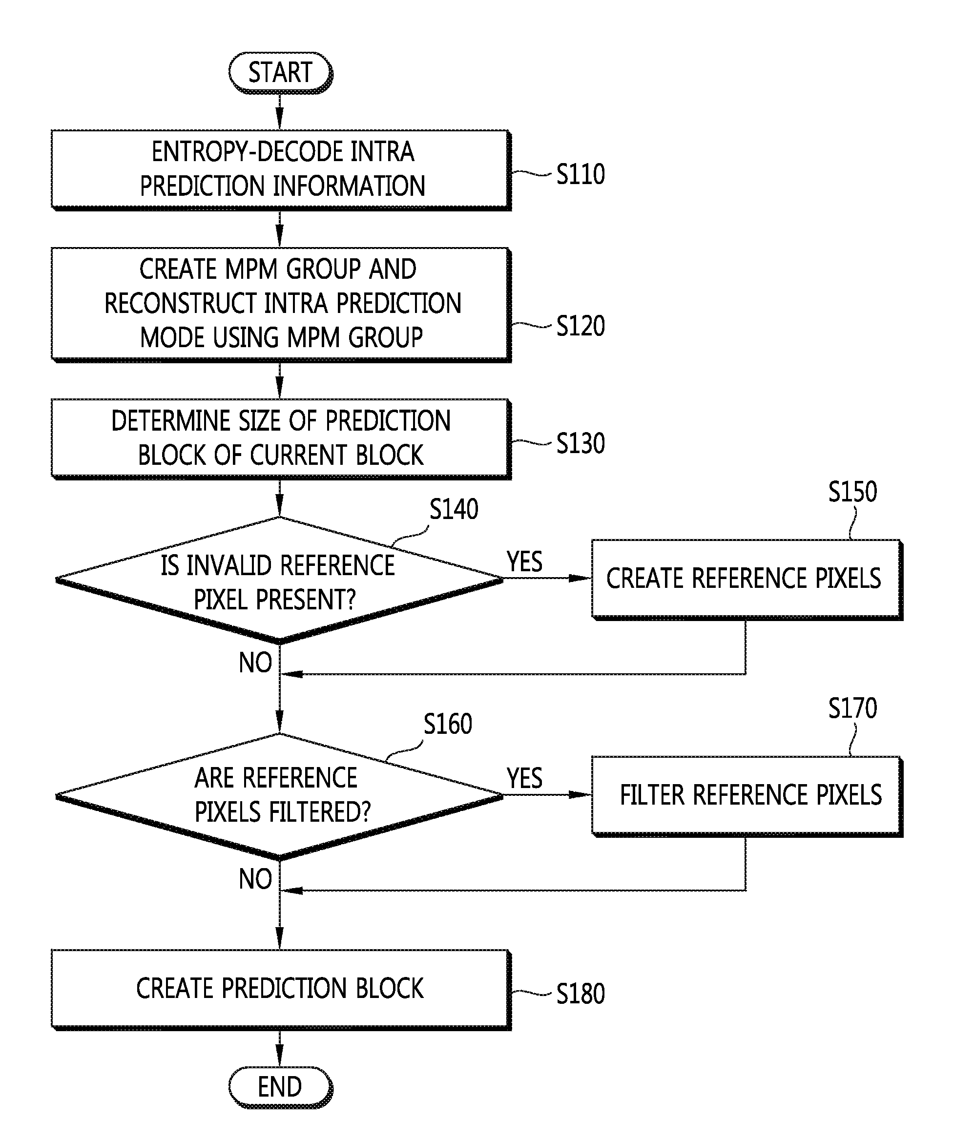
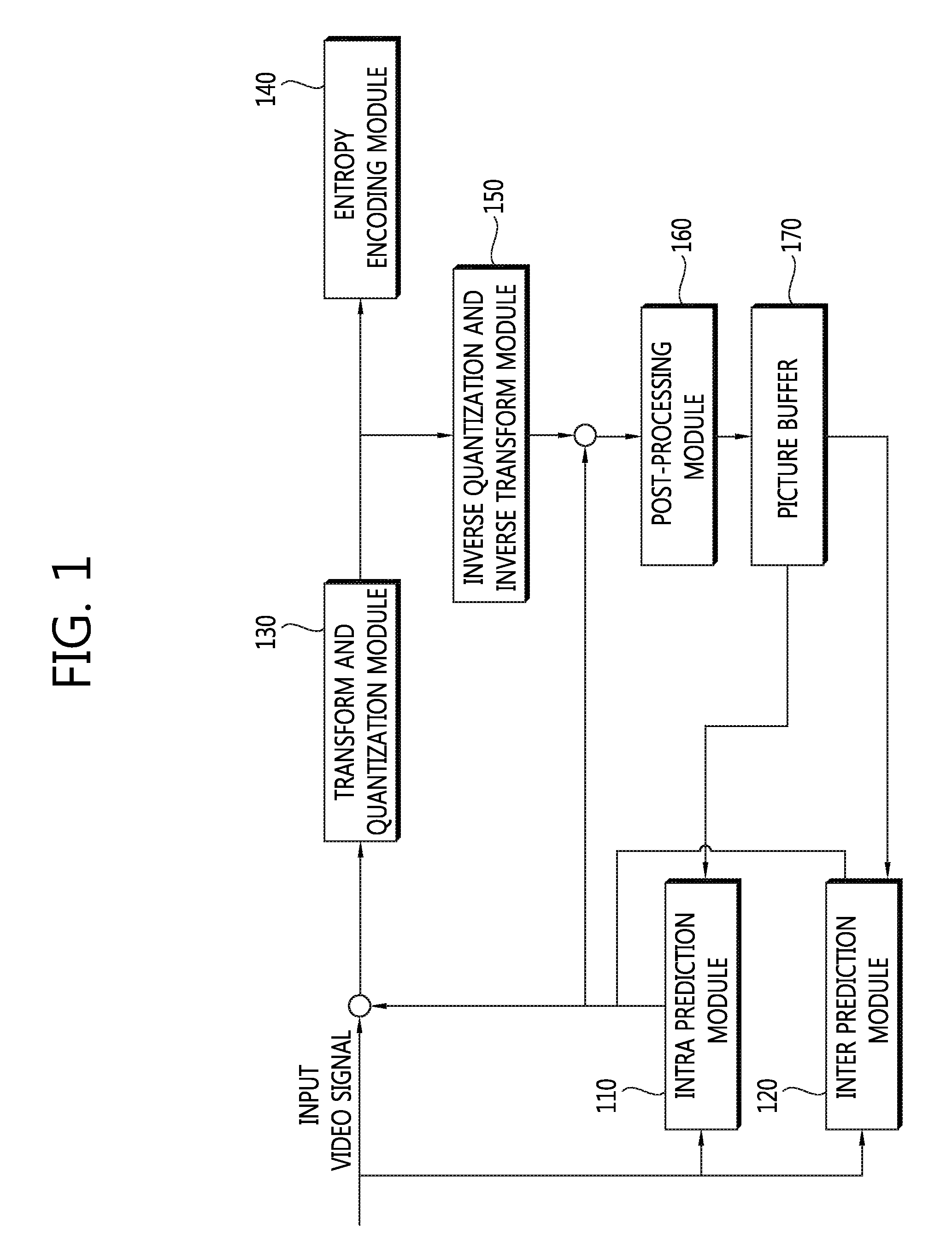
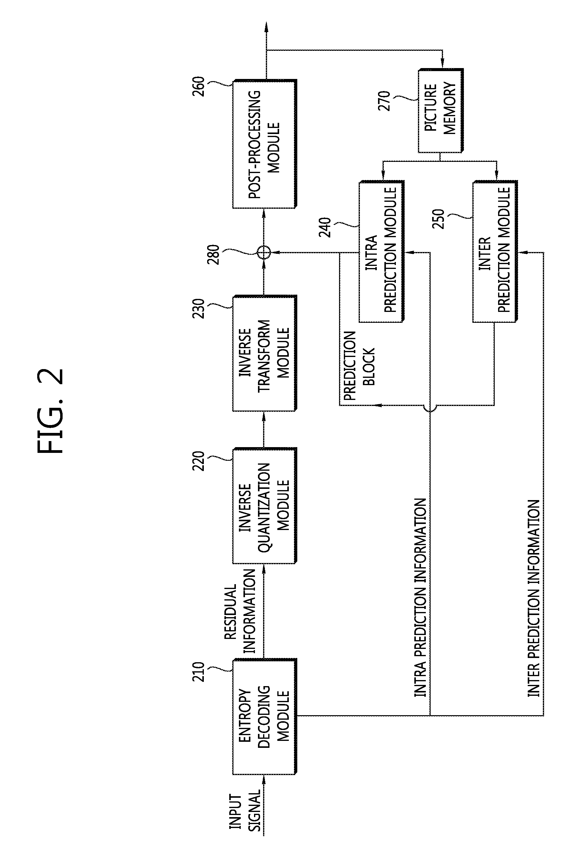
[0011]The image decoding device according to the invention includes an intra prediction module for reconstructing an intra prediction mode and creating a prediction block of a current block or a sub block of the current block, an inverse scanning module for converting residual signals into a two-dimensional quantization block, an inverse quantization module for inversely quantizing the quantization block using the quantization parameter, and an inverse transform module for inversely-transforming the inversely-quantized block. A quantization parameter predictor used for deriving the quantization parameter is created using a quantization parameter of a left coding unit of a current coding unit and a quantization parameter of a top coding unit of the current coding unit.
[0012]Therefore, it is possible to improve image quality by adaptively adjusting a quantization parameter of a current block depending on the size of a coding unit and to enhance compression efficiency of an image by effectively encoding / decoding the quantization parameter to reduce the number of bits required for transmitting the quantization parameter.

Problems solved by technology

However, in H.264, the intra prediction mode of a current block is encoded regardless of directivity of the intra prediction modes of the left and top blocks of the current block and there is thus a problem in that the encoding efficiency is low.
However, in this case, a large number of bits are required to transmitting the quantization parameter.

Method used


Image

  • Imaging decoding apparatus
  • Imaging decoding apparatus
  • Imaging decoding apparatus

Examples


Embodiment Construction

[0020]Hereinafter, various embodiments of the invention will be described in detail with reference to the accompanying drawings. The invention can be modified in various forms and can have various embodiments. The embodiments are not intended for limiting the invention, but it should be understood that the invention includes all the modifications, equivalents, and replacements belonging to the spirit and the technical scope of the invention. In description of the invention with reference to the drawings, like constituents are referenced by like reference numerals.

[0021]A moving image encoding device and a moving image decoding device according to the invention may be user terminals such as a personal computer, a notebook PC, a personal digital assistant, a portable multimedia player, a smart phone, a wireless communication terminal, and a TV or servers providing services. The moving image encoding device and the moving image decoding device may be apparatuses having a communication ...


PUM


Abstract

An image decoding device is provided which includes an intra prediction module for reconstructing an intra prediction mode and creating a prediction block of a current block or a sub block, an inverse scanning module for converting residual signals into a quantization block, an inverse quantization module for inversely quantizing the quantization block, and an inverse transform module for inversely-transforming the inversely-quantized block. A quantization parameter predictor for deriving the quantization parameter is created using quantization parameters of a left coding unit and a top coding unit of a current coding unit. Therefore, it is possible to improve image quality by adaptively adjusting a quantization parameter of a current block depending on the size of a coding unit and enhance compression efficiency of an image by effectively encoding / decoding the quantization parameter to reduce the number of bits required for transmitting the quantization parameter.

Description

CROSS-REFERENCE TO RELATED PATENT APPLICATIONS[0001]This application is a 35 U.S.C. §371 national stage filing of International Application No. PCT / KR2012 / 003085, filed Apr. 20, 2012, which claims the benefit of Korean Patent Application No. 10-2011-0108456, filed on Oct. 24, 2011 and Korean Patent Application No. 10-2011-0108460, filed on Oct. 24, 2011. The contents of each of the foregoing applications are incorporated herein by reference in their entireties.TECHNICAL FIELD[0002]The present invention relates to an image decoding device, and more particularly, to a device that uses quantization parameters of left and top coding units to derive a quantization parameter predictor used for generating a residual block.BACKGROUND ART[0003]Image data has to be encoded to efficiently store or transmit the image data. MPEG-1, MPEG-2, MPEG-4, H.264 / MPEG-4 AVC (Advanced Video Coding), and the like are known as techniques of encoding image data. In these techniques, a picture is divided into ...

Claims


Application Information

Patent Timeline
Patent Type & Authority Patents(United States)
IPC IPC(8): H04B1/66H04N19/196H04N19/126H04N11/04H04N11/02H04N7/12H04N19/463H04N19/157H04N19/124H04N19/60H04N19/593H04N19/11H04N19/44H04N19/176
CPCH04N19/126H04N19/124H04N19/157H04N19/196H04N19/463H04N19/11H04N19/176H04N19/198H04N19/44H04N19/593H04N19/60H04N19/146H04N19/50H04N19/45H04N19/159
Inventor PARK, SHIN, JI
Owner GENSQUARE LLC
Learn More