Pressure actuated valve for multi-chamber syringe applications

a technology of pressure actuation valve and multi-chamber syringe, which is applied in the field of valves, can solve problems such as unsatisfactory basic operational criteria

Inactive Publication Date: 2016-03-22
THORNE CONSULTING & INTPROP
View PDF14 Cites 5 Cited by
  • Summary
  • Abstract
  • Description
  • Claims
  • Application Information

AI Technical Summary

Benefits of technology

[0024]It may be noted that pressure within the hollow chamber decompresses the chamber once pressure external to the valve is relieved. To aid recovery of chamber size and shape following application of external pressure, the inserted tube may be frustoconicallly shaped. In this case, energy required to force the external tube about the internal tube is stored to resultantly act to force displacement of the internal tube relative to the external tube toward an initial state. It may be noted that a spring disposed to be compressed when the inserted tube is move further into the external tube may also be used to provide energy to force tube positioning toward the initial state.
[0033]Mixing operation of the combination mixing and sequential delivery syringe is substantially identical to mixing operation of the simple mixing syringe. It should be noted, however, that upon fully dispensing liquid from the middle chamber (the more proximal chamber in the simple mixing syringe), the mixing syringe valve and sequential delivery syringe valves are preferably driven together, thus eliminating the middle chamber.
[0053]displacing a displacement actuated valve proximal to the first proximal chamber to provide a more proximal chamber within the syringe barrel and cause the first proximal chamber to become a middle chamber;

Problems solved by technology

While the above cited art, and other art generally related, provide a basis for commercial devices, there are some basic operational criteria which are not completely met by any prior art.

Method used


Image

  • Pressure actuated valve for multi-chamber syringe applications
  • Pressure actuated valve for multi-chamber syringe applications
  • Pressure actuated valve for multi-chamber syringe applications

Examples


Embodiment Construction

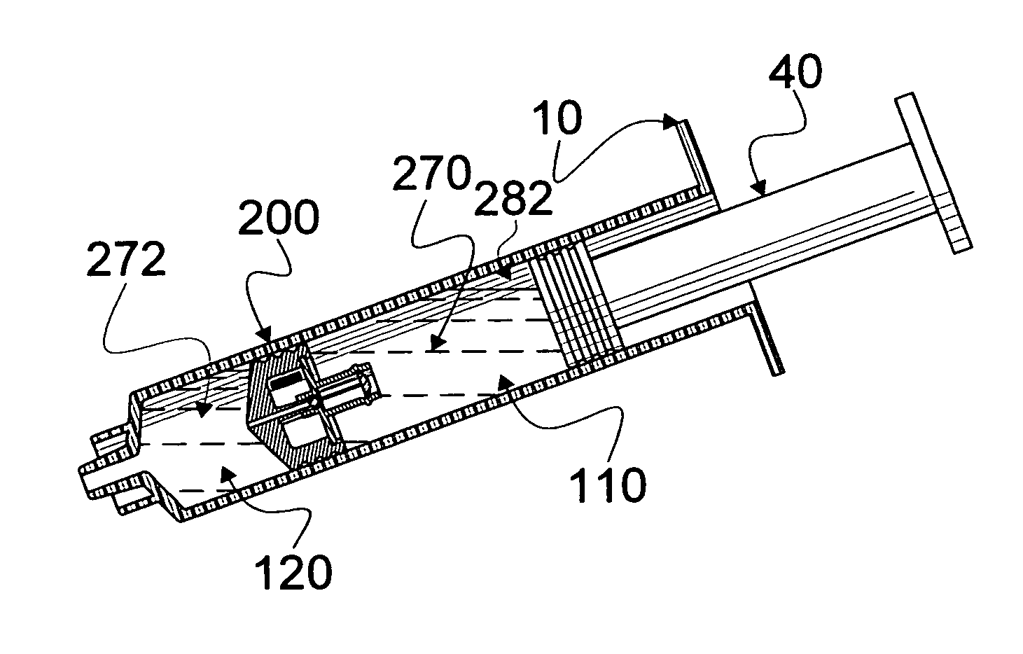
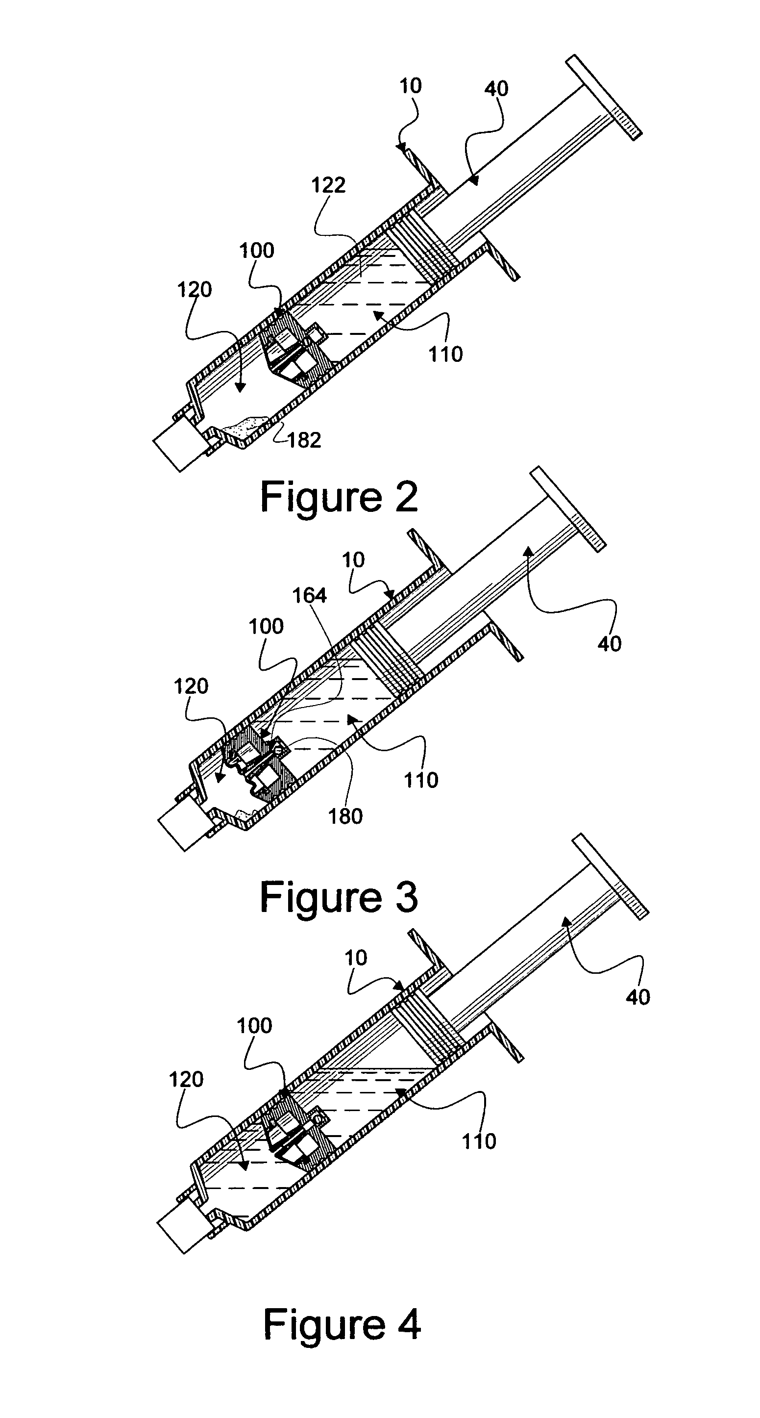
[0113]Reference is now made to the embodiments illustrated in FIGS. 1-43 wherein like numerals are used to designate like parts throughout. Primes of numbers are used to indicate an item which is like another item so numbered but having one or more elements of differentiation.

Mixing Syringe Embodiment

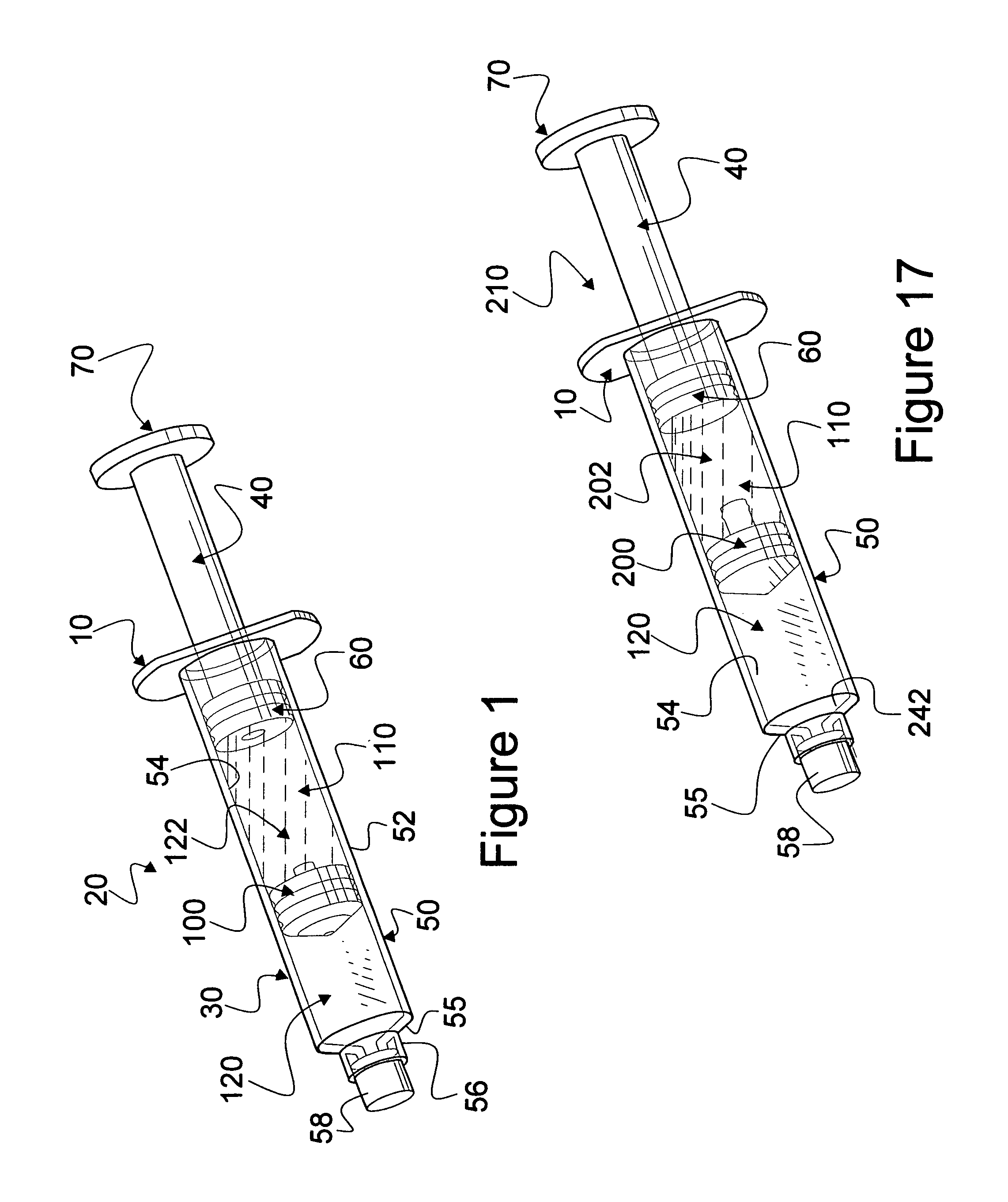
[0114]Reference is now made to FIGS. 1-16 wherein mixing syringe embodiments are seen. Using a pressure actuated valve, a conventional syringe 10 may be employed in construction of a mixing syringe 20, as seen in FIG. 1. Syringe 10 is generally provided with a barrel part 30 and a plunger and rod assembly 40. Barrel part 30 comprises a barrel 50 which is an elongated hollow tube 52 with a smooth, circular inner surface 54 which is substantially of constant diameter and obstructed at a distal end 55 at a luer fitting 56 by a cap 58.

[0115]Plunger and rod assembly 40 is usually constructed with two parts, a plunger 60 and an elongated rod 70 by which plunger 60 is displaced within syringe ...


PUM


Abstract

Methods and apparatus are disclosed for disposing a valve within a barrel of a conventional syringe to provide, first, a mixing syringe embodiment and, second, a sequential delivery syringe embodiment. Generally, the valve divides the syringe barrel into a proximal and a distal chamber. When used for mixing, the valve is self-displaceable by expansion of decompressing matter disposed within the valve against exterior matter permitting proximal displacement of the valve independent of character of matter in the distal chamber. For sequential delivery, switching of the valve occurs after switch opening causing pressure is relieved, thereby reducing inadvertent uncontrolled flow when the valve opens. In addition, a combination mixing and flush syringe is disclosed whereby a mixing and a flush capability is provided within a conventional syringe.

Description

CONTINUATION-IN-PART[0001]This Patent Application is a Continuation-in-Part of U.S. patent application Ser. No. 13 / 066,565, titled MEDICAL SYRINGE PRIME AND CROSS-CONTAMINATION FREE DEVICES filed Apr. 18, 2011, by Gale H. Thorne, Jr. et al. (Thorne Application).FIELD OF INVENTION[0002]This invention relates to valves which are disposed in conventional medical syringes to provide either multi-chamber sequential delivery or mixing syringes or combinations of mixing and sequential delivery syringes.BACKGROUND AND DESCRIPTION OF RELATED ART[0003]Four U.S. Patents which are related to the instant inventions disclosed herein are U.S. Pat. No. 6,997,910 B2, titled MULTI-CHAMBER SEQUENTIAL DOSE DISPENSING SYRINGE, filed May 3, 2004 and issued Feb. 14, 2006, to Michael Wallace Howlette, et al. (Howlette 910); U.S. Pat. No. 7,048,720 B1, titled MULTI-CHAMBER DOSE DISPENSING SYRINGE, filed Nov. 22, 2005 and issued May 23, 2006 to Gale H. Thorne, et al. (Thorne 720); U.S. Pat. No. 7,789,862 B2,...

Claims


Application Information

Patent Timeline
Patent Type & Authority Patents(United States)
IPC IPC(8): A61M5/178A61M5/315A61M5/36A61M5/19A61M5/31
CPCA61M5/19A61M5/31511A61M5/31596A61M2005/1787A61M2005/3121
Inventor THORNE, JR., GALE H.THORNE, GALE H.
Owner THORNE CONSULTING & INTPROP
Why Eureka
Try Eureka