Position-limit hinge

a technology of hinge shaft and limiting plate, which is applied in the field of hinge technology, can solve the problems of inability to accurately synchronize the rotation of the hinge shaft, the damage of the beauty sense, and the idle stroke of the link, and achieve the effect of smooth opening

Inactive Publication Date: 2016-03-22
HORNG CHIN HSING
View PDF40 Cites 39 Cited by
  • Summary
  • Abstract
  • Description
  • Claims
  • Application Information

AI Technical Summary

Benefits of technology

[0005]The present invention has been accomplished under the circumstances in view. It is therefore the main object of the present invention to provide a position-limit hinge, which uses a first position-limit device set and a second position-limit device set to let a first hinge shaft to be rotated or an axle housing to be turned about a second hinge shaft, enabling a cover member of an electronic device carrying the position-limit hinge to be smoothly opened relative to a base member.

Problems solved by technology

However, when turned the cover member through 180°, the cover member and the base member are not kept on a plane, leading to the destruction of the sense of beauty.
However, the use of the link can produce an idle stroke, i.e., the first hinge shaft and the second hinge shaft cannot be accurately synchronously rotated for enabling the cover member to be turned smoothly.
However, reducing the size of the hinge will relatively reduce the strength of the link, and the link can easily be forced to break by an external force.

Method used


Image

  • Position-limit hinge
  • Position-limit hinge
  • Position-limit hinge

Examples


first embodiment

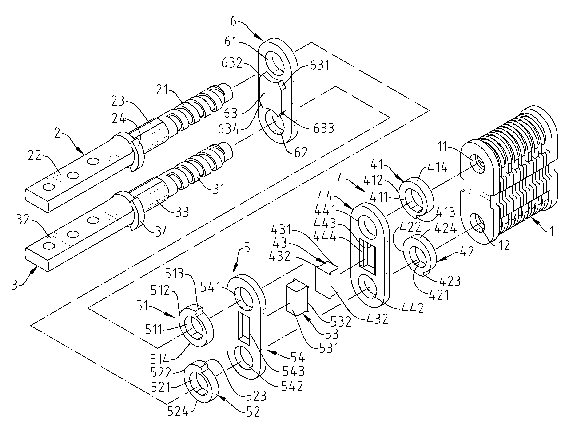
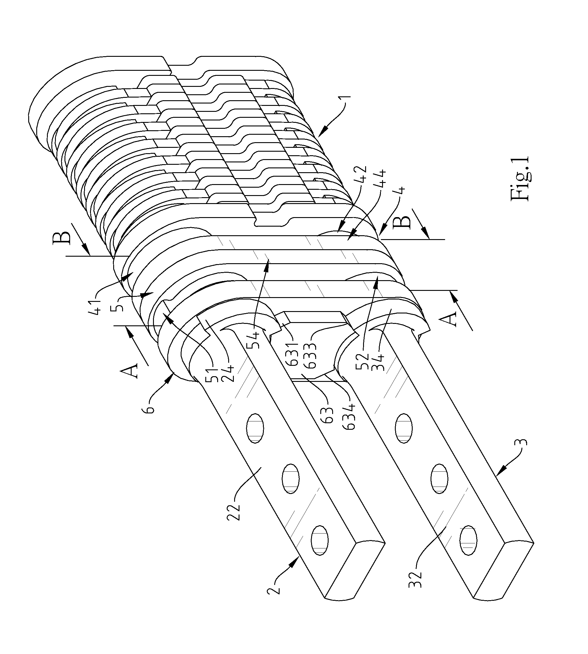
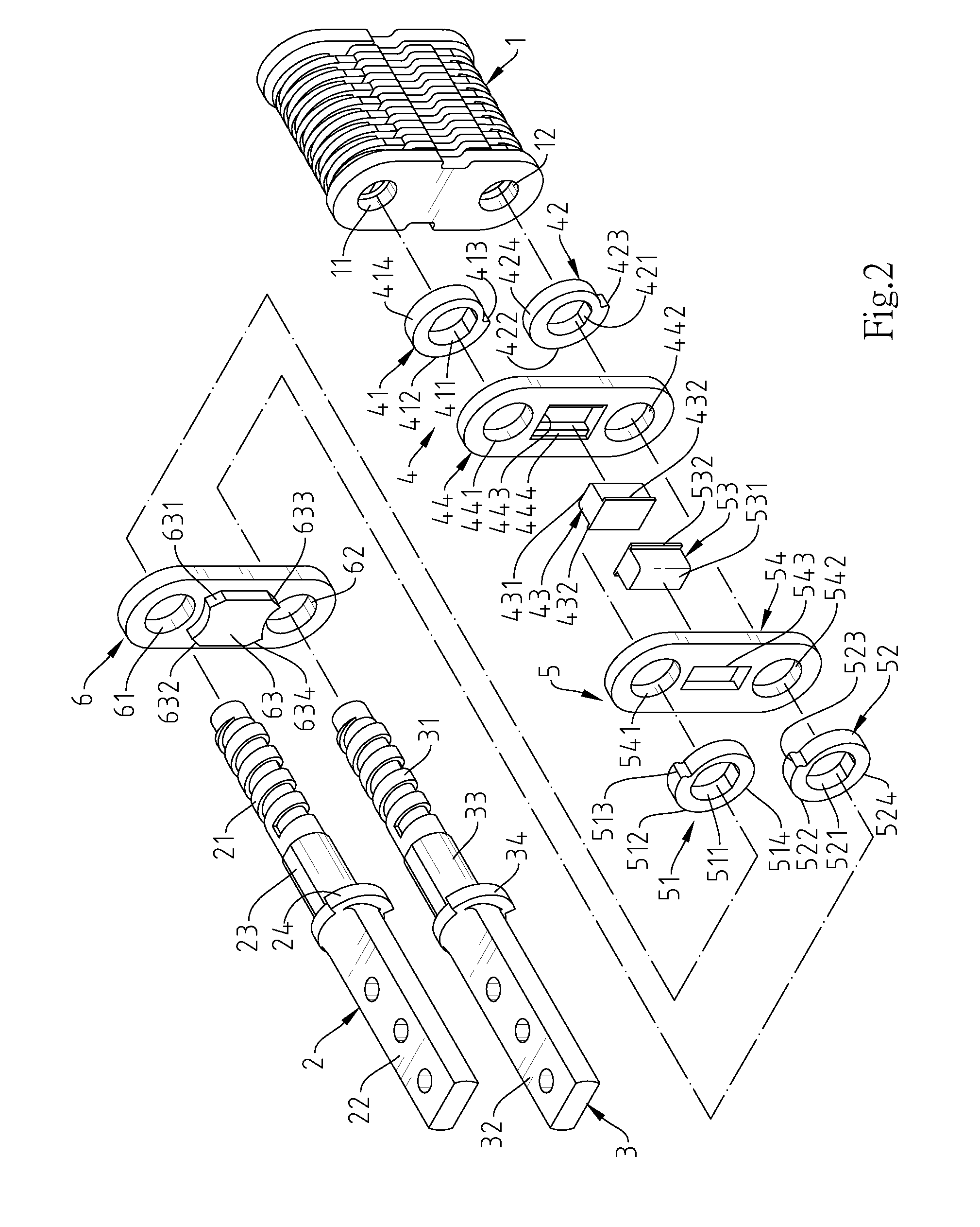
[0036]Referring to FIGS. 1-8, a position-limit hinge in accordance with the present invention is shown. The position-limit hinge comprises an axle housing 1, a first hinge shaft 2, a second hinge shaft 3, a first position-limit device set 4 a second position-limit device set 5, and a positioning member 6.

[0037]The axle housing 1 defines therein a first axle hole 11 and a second axle hole 12.

[0038]The first hinge shaft 2 comprises a first shaft portion 21 located at one end thereof and rotatably inserted into the first axle hole 11 of the axle housing 1, a first mounting portion 22 located at an opposite end thereof and fixedly fastened to a cover member 71 of an electronic device 7 and exposed to the outside of the axle housing 1, a first position-limit portion 23 connected between the first shaft portion 21 and the first mounting portion 22 and exposed to the outside of the axle housing 1, and a first stop flange 24 extending around the periphery thereof between the first mounting ...

second embodiment

[0044]Referring to FIGS. 18-26, in the present invention, the distance between the third lower limit position 914 of the third cam wheel 91 of the second position-limit device set 9 and the fourth upper limit position 923 of the fourth cam wheel 92 at the initial point is larger than the distance between the opposing top and bottom sides of the second body 931, therefore a gap exists between the third cam wheel 91 and the second body 931, allowing the second position-limit device set 9 to be freely rotated; the distance between the first upper limit position 813 of the first cam wheel 81 of the first position-limit device set 8 and the second lower limit position 824 of the second cam wheel 82 at the initial point is equal to the distance between the opposing top and bottom sides of the first body 831, therefore the first upper limit position 813 and the second lower limit position 824 are respectively stopped at the opposing top and bottom sides of the first body 831, and thus, rot...


PUM


Abstract

A position-limit hinge includes an axle housing, a first hinge shaft, a second hinge shaft, a first position-limit device set and a second position-limit device set. By means of enabling the first position-limit device set and the second position-limit device set to be alternatively changed between a position-limit status and a freely rotatable status, the first hinge shaft is driven to rotate or the axle housing is driven to turn about the second hinge shaft, enabling a cover member of an electronic device carrying the position-limit hinge to be smoothly opened relative to a base member.

Description

BACKGROUND OF THE INVENTION[0001]1. Field of the Invention[0002]The present invention relates to hinge technology and more particularly, to a position-limit hinge for use in a dual-leaf electronic device, which allows the cover member of the dual leaf electronic device to be turned from the top side of the base member to the bottom side thereof.[0003]2. Description of the Related Art[0004]A dual-leaf electronic device such as notebook computer, smart phone, etc. generally comprises a base member and a cover member, wherein the cover member of the electronic device can be turned from the top side of the base member to the bottom side thereof, enabling the electronic device to be used as a tablet computer. A dual-leaf electronic device uses a dual-shaft hinge for enabling the cover member thereof to be turned through 360°. When opening the cover member of the dual-leaf electronic device through 360°, the first hinge shaft is rotated through 180° and then the second hinge shaft is rota...

Claims


Application Information

Patent Timeline
Patent Type & Authority Patents(United States)
IPC IPC(8): E05D3/12E05D11/06E05D3/06G06F1/16
CPCE05D3/12G06F1/1681E05D11/06E05D3/06Y10T16/5478G06F1/1618G06F1/1616Y10T16/547G06F1/162
Inventor HORNG, CHIN-HSING
Owner HORNG CHIN HSING
Why Eureka
Try Eureka