Directionally reversible hot air engine system

a hot air engine and directional reversible technology, applied in the direction of machines/engines, hot gas positive displacement engine plants, solar thermal energy generation, etc., can solve the problem that one cannot actually determine the thermal efficiency of an engine withou

Active Publication Date: 2016-03-22
FOUNTAIN DANIEL L
View PDF1 Cites 2 Cited by
  • Summary
  • Abstract
  • Description
  • Claims
  • Application Information

AI Technical Summary

Problems solved by technology

One cannot actually determine the thermal efficiency of an engine without an understanding of these basic thermodynamic principles.
Challenges arise in that no engine or heat pump made looks and works like the ideal schematic representation.

Method used


Image

  • Directionally reversible hot air engine system
  • Directionally reversible hot air engine system
  • Directionally reversible hot air engine system

Examples


Embodiment Construction

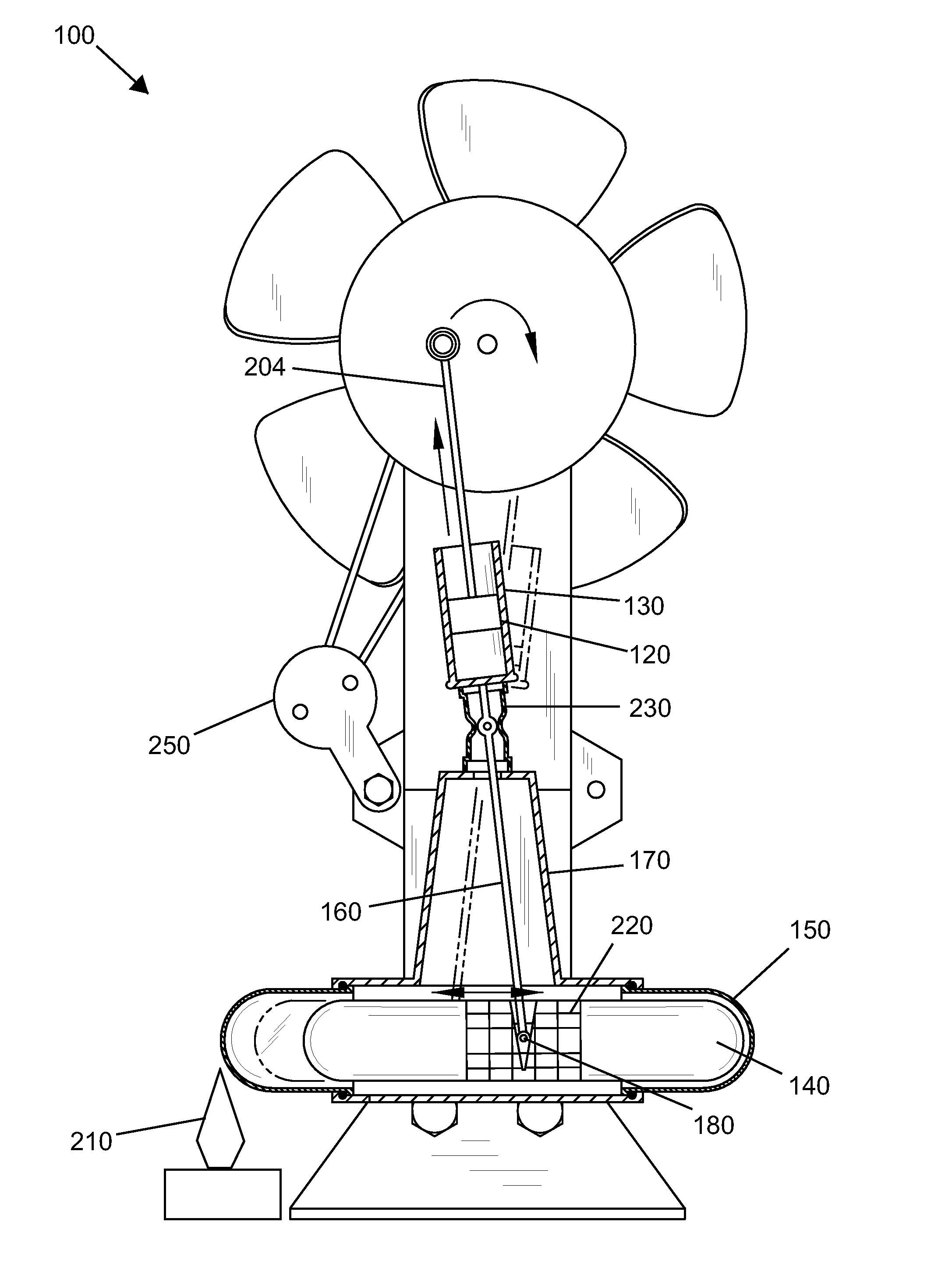
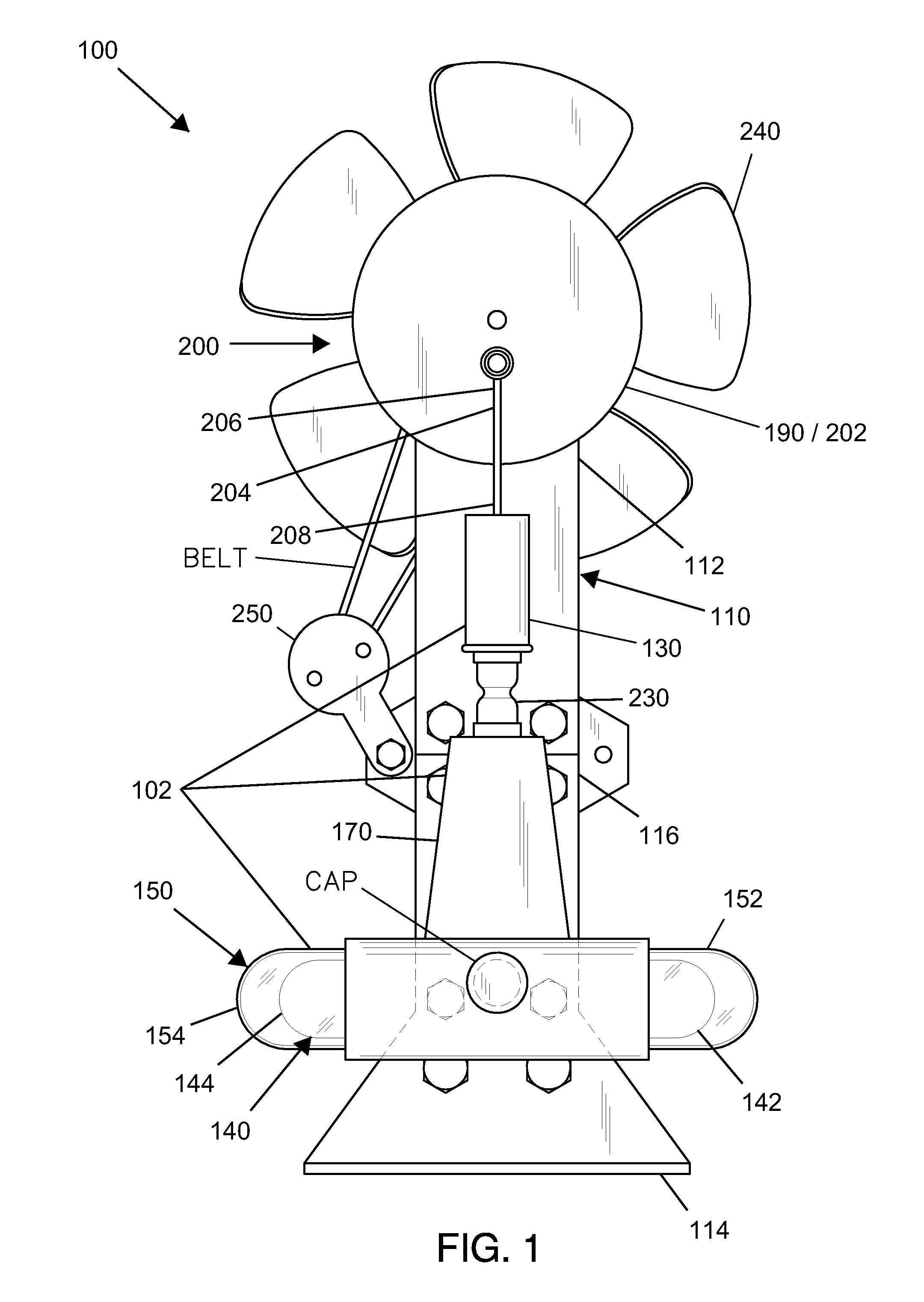
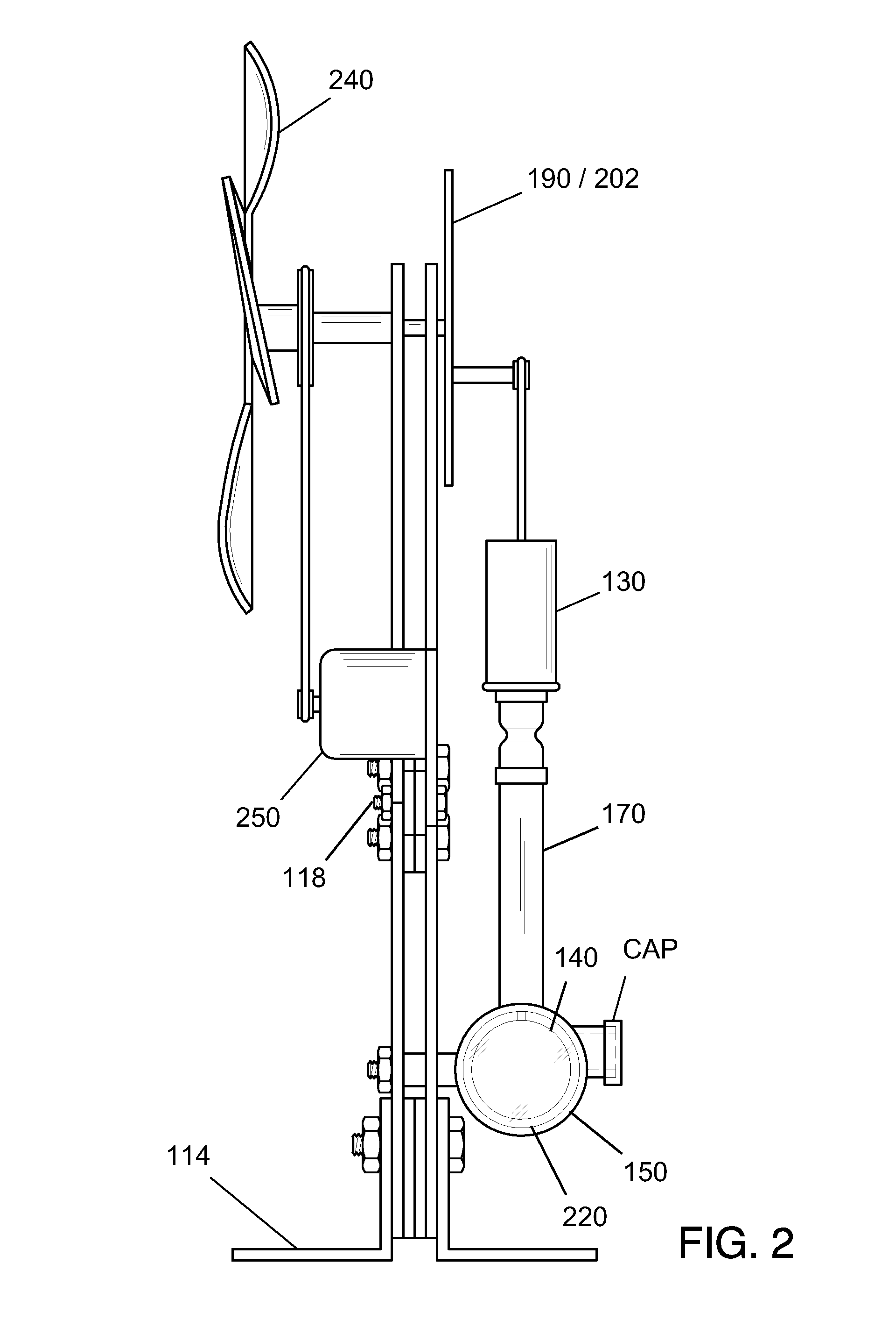
[0018]Following is a list of elements corresponding to a particular element referred to herein:[0019]100 Hot air engine system[0020]102 System chamber[0021]110 Frame[0022]112 Frame top[0023]114 Frame bottom[0024]116 Frame middle[0025]118 Frame attachment and adjustment bolt[0026]120 Piston[0027]122 Piston first end[0028]124 Piston second end[0029]130 Piston cylinder[0030]140 Displacer[0031]142 Displacer first end[0032]144 Displacer second end[0033]146 Displacer middle[0034]150 Displacer chamber[0035]152 Chamber first end[0036]154 Chamber second end[0037]156 Chamber middle[0038]160 Rod[0039]162 Rod first end[0040]164 Rod second end[0041]170 Rod housing[0042]180 Hinge[0043]190 Flywheel[0044]200 Crank[0045]202 Wheel[0046]204 Crank rod[0047]206 Crank rod first end[0048]208 Crank rod second end[0049]210 Heat source[0050]220 Regenerator[0051]230 Rubber boot[0052]240 Fan blade[0053]250 Generator

[0054]Referring now to FIG. 1-5, the present invention features a directionally reversible hot a...


PUM


Abstract

A reversible hot air engine system having operating modes for both engine and heat pump operation features a piston located in a piston cylinder that is located on a frame. The system features a displacer located in a displacer chamber that is horizontally located at a frame bottom. A rod first end is pivotally located on a piston second end. A rod second end is pivotally located on a displacer middle via a hinge. A rod housing is fluidly connected to the displacer chamber and the piston cylinder. The system features a flywheel located at a frame top. The system features, a crank having a wheel eccentrically and pivotally connected to a crank rod first end. A crank rod second end is pivotally located to a piston first end. The system features a heat source applied to a chamber end.

Description

CROSS REFERENCE[0001]This application claims priority to U.S. Patent Application No. 61 / 834,781, filed Jun. 13, 2013, the specification(s) of which is / are incorporated herein in their entirety by reference.FIELD OF THE INVENTION[0002]The present invention relates to hot air engines.BACKGROUND OF THE INVENTION[0003]Hot air engines have been around for approximately two hundred years in many successful designs. Hot air engines derive their power from the expansion and contraction of a gas, usually air that is heated and cooled to ultimately drive a crank. Many hot air engines work in a thermodynamic process knows as a Stirling cycle, named after Robert Stirling, a 19th century inventor.[0004]All heat engines take a certain amount of heat and convert a percentage into work, while rejecting the remaining energy at a lower temperature. Schematically, as heat moves through the engine, from the hot to the cold side, the engine converts some of that energy into work. The key is that only a ...

Claims


Application Information

Patent Timeline
Patent Type & Authority Patents(United States)
IPC IPC(8): F02G1/04F02G1/043
CPCF02G1/0435F02G1/043F02G1/04F02G1/00F02G2270/42F03G6/068Y02E10/46
Inventor FOUNTAIN, DANIEL, L.
Owner FOUNTAIN DANIEL L
Why Eureka
Try Eureka