

Conveyance seat
a technology for vehicles and seats, applied in the field of vehicles, can solve the problems of reducing the ease of getting in and out of the vehicle, and achieve the effects of improving ease and safety, and improving ease and safety
- Summary
- Abstract
- Description
- Claims
- Application Information
AI Technical Summary
Benefits of technology
Problems solved by technology
Method used
Image

Examples
Embodiment Construction
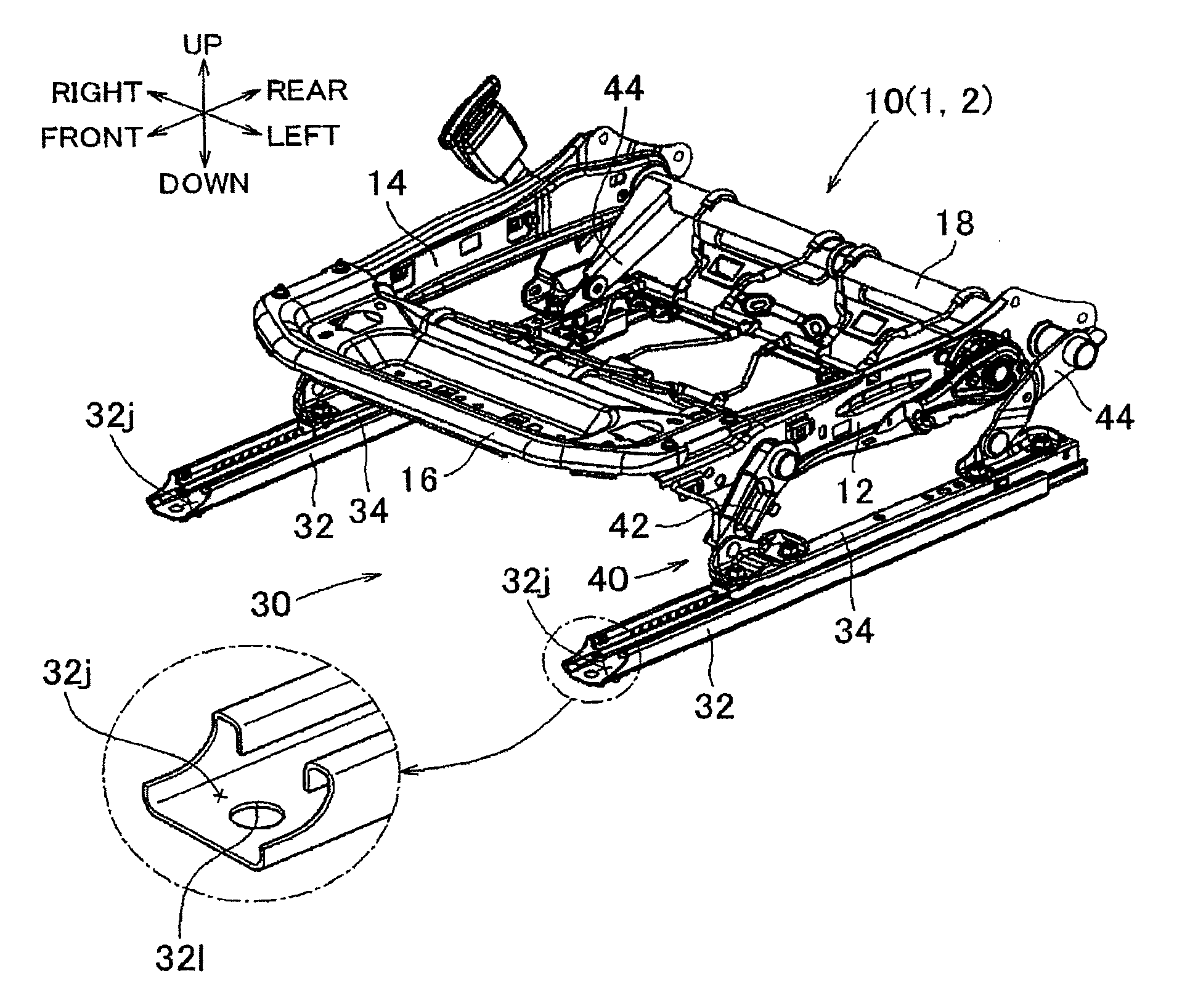
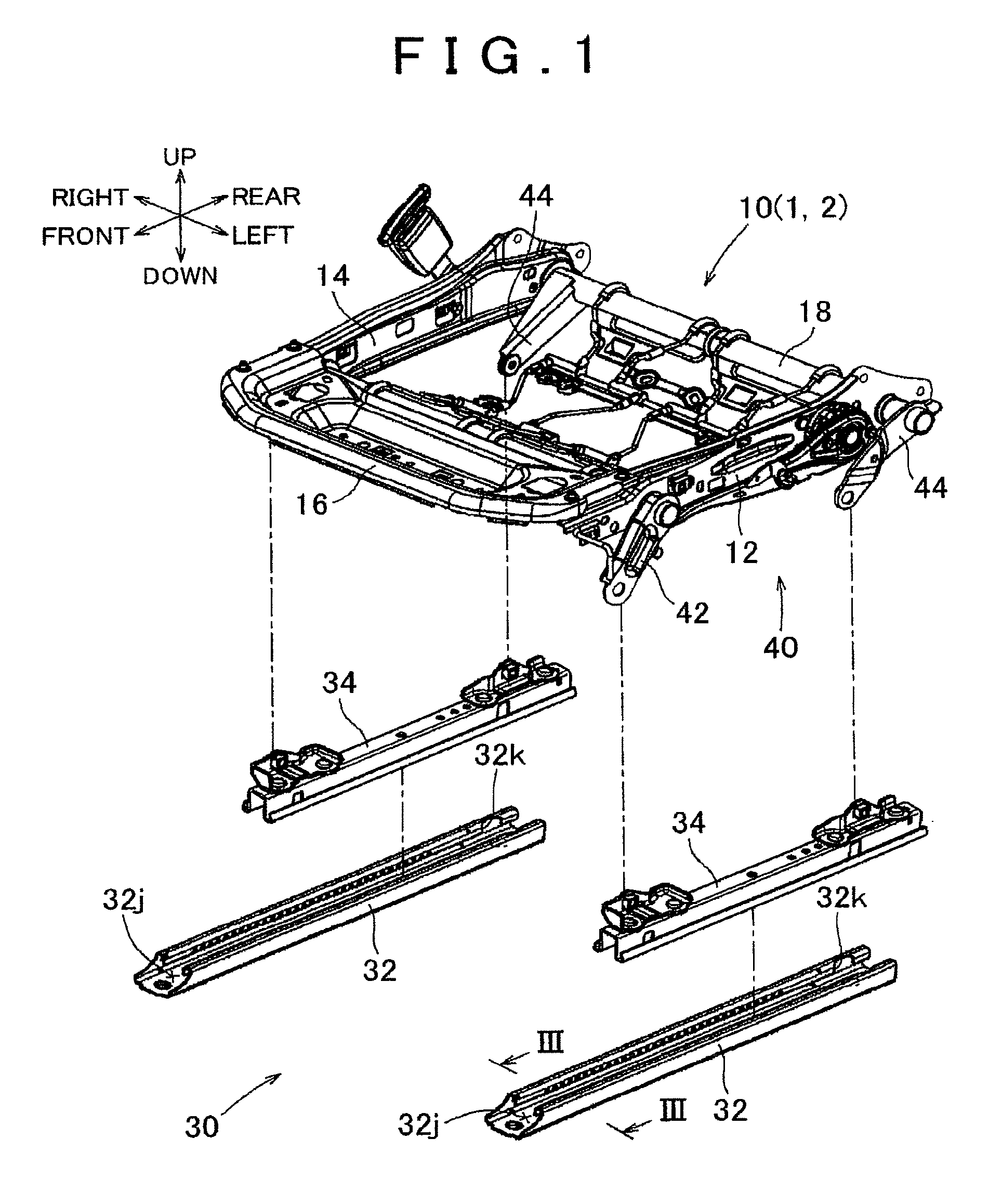
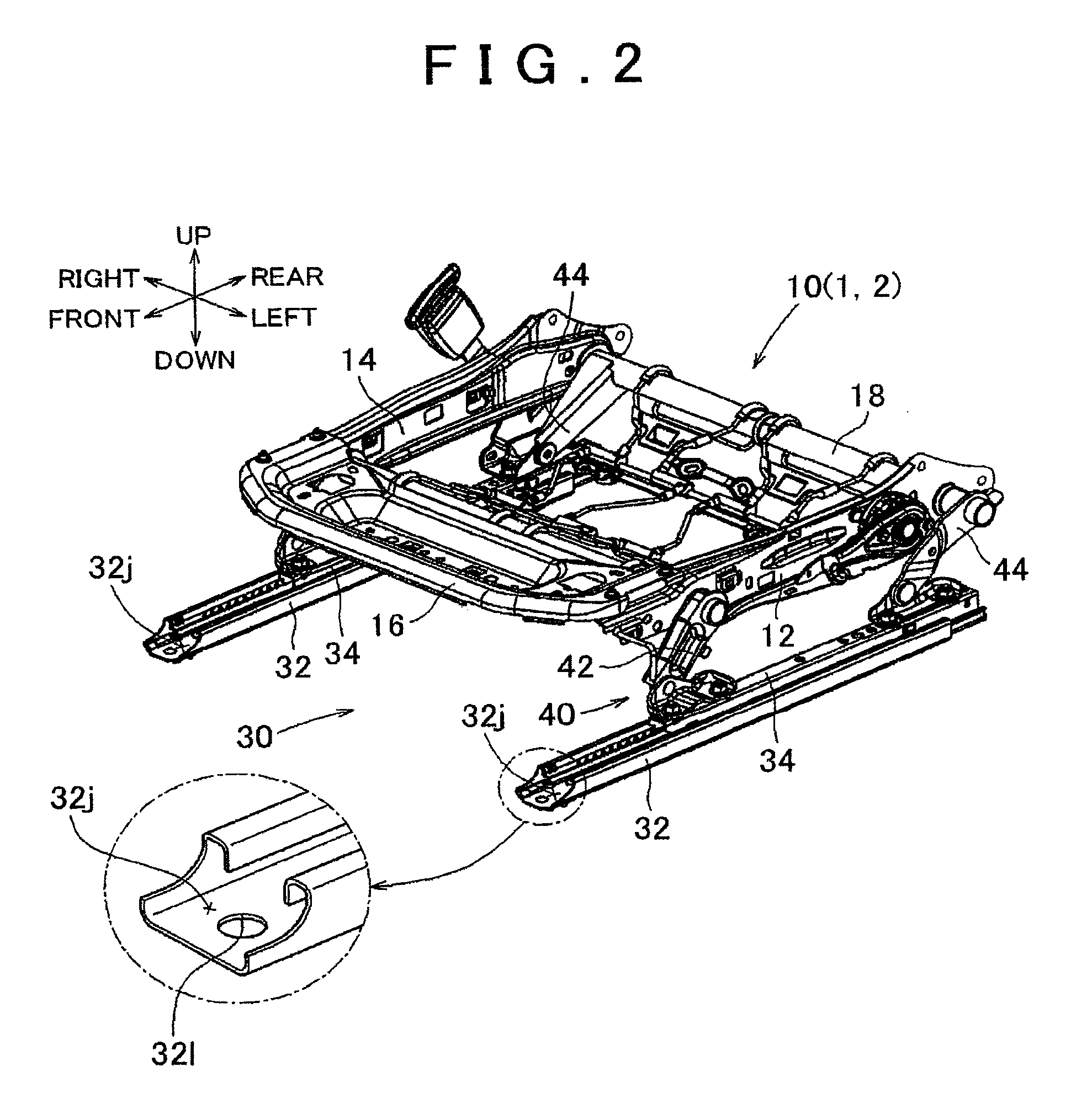
[0018]Referring to FIG. 1 through FIG. 4, one embodiment of the invention will be described. In the following description, “vehicle seat 1” will be described as an example of “conveyance seat”. Also, in the following description, the terms “up”, “down”, “front”, “rear”, “left” and “right” indicate respective directions denoted by arrows labelled “up”, “down”, “front”, “rear”, “left” and “right” in FIGS. 1 to 4, namely, upward, downward, forward, and rearward from the vehicle seat 1 when installed inside a vehicle (not shown), and to the left and the right of the vehicle seat 1, respectively.
[0019]Referring first to FIGS. 1-2, the construction of the vehicle seat 1 will be described. The vehicle seat 1 is a passenger seat (the left-hand seat in the vehicle compartment in this embodiment), and consists principally of a seat cushion 2 and a seat back (not shown). In the following, the seat cushion 2, out of the seat cushion 2 and the seat back (not shown), will be described in detail. ...
PUM
 Abstract
Description
Claims
Application Information