Detection of obstacles at night by analysis of shadows

a shadow edge and obstacle detection technology, applied in the field of driver assistance systems, can solve the problems of only available depth information on the shadow edge, limited detection range of drop-offs,

Active Publication Date: 2016-03-29
MOBILEYE VISION TECH LTD
View PDF8 Cites 101 Cited by
  • Summary
  • Abstract
  • Description
  • Claims
  • Application Information

AI Technical Summary

Problems solved by technology

The range of detection of drop-offs is limited to a few meters since texture is required for stereo and motion correspondence.
Furthermore, depth information on the shadow edge is only available when the light sources are displaced along the stereo baseline.

Method used


Image

  • Detection of obstacles at night by analysis of shadows
  • Detection of obstacles at night by analysis of shadows
  • Detection of obstacles at night by analysis of shadows

Examples


numerical example

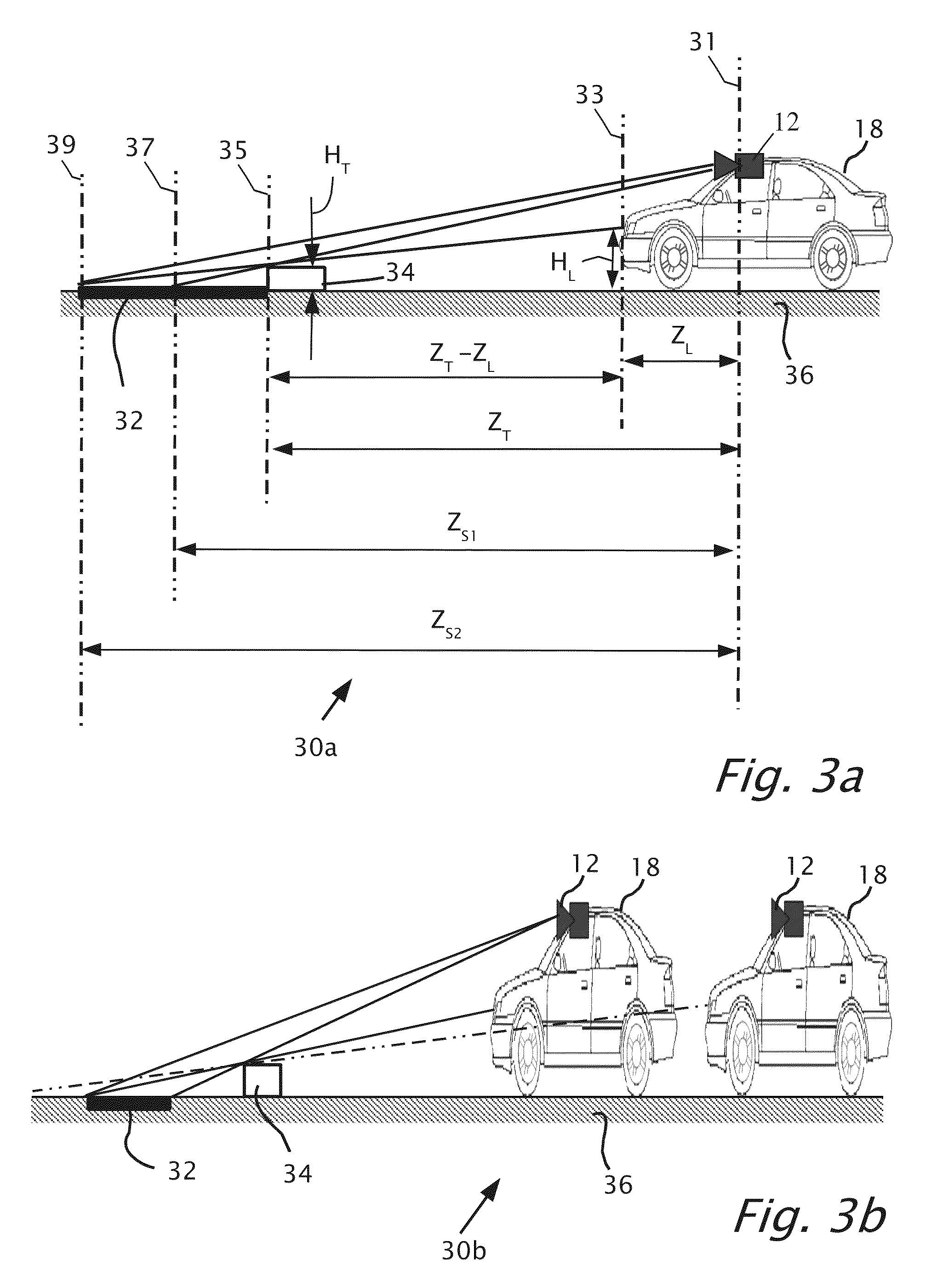
[0070]Reference is now made to FIG. 7 which shows a graph 70 for a simulation, according to a feature of the present invention. Graph 70 plots two curves, one for a patch or road mark (dotted line) and one for a shadow strip (solid line). The thickness of the patch or shadow strip is in pixels versus range to obstacle in meters (m). The simulation has camera 12 mounted in a Renault Megane II where HC=1.25 m, HL=0.73 m and obstacle of height HT=0.1 m. A shadow will appear just over 2 pixels thick at 50 m. At 25 m the shadow will double in size to about 4 pixels. A road mark on road at 25 m will quadruple in size to 8 pixels.

[0071]Note that at a certain close distance (≈5 m) the tangent line of the headlight and of the camera 12 coincide. After passing 5 m the size of the shadow patch decreases rapidly.

[0072]Referring back to FIGS. 3a and 3b, FIGS. 3a and 3b show a step edge drop. The step edge drop is typical for a pot hole, road edge and steep speed bump. With the step edge drop, th...


PUM


Abstract

A driver assistance systems mountable in a host vehicle while the host vehicle is moving forward with headlights on for detection of obstacles based on shadows. The driver assistance system includes a camera operatively connectible to a processor. A first image frame and a second image frame are captured of a road. A first dark image patch and a second dark image patch include intensity values less than a threshold value. The first and the second dark image patches are tracked from the first image frame to the second image frame as corresponding images of the same portion of the road. Respective thicknesses in vertical image coordinates are measured of the first and second dark image patches responsive to the tracking.

Description

CROSS REFERENCE TO RELATED APPLICATIONS[0001]The present application claims priority from US provisional application 61 / 569,306 filed Dec. 12, 2011 and from U.S. provisional application 61 / 702,755 filed Sep. 19, 2012 which are included herein by reference.BACKGROUND[0002]1. Technical Field[0003]The present invention relates to the field of driver assistance systems (DAS) and in particular to detection of obstacles in a road using a camera.[0004]2. Description of Related Art[0005]Larson et al. [1] perform detection of negative obstacles using LIDAR and other three dimensional data. Belutta et al. [2] detect depth discontinuities of negative obstacles from stereo range data. Rabkin et al. [3] use stereo range data on thermal cameras because the shape of the terrain also affects the thermal properties. Muraka et al. [4] combine stereo and motion information to detect discontinuities in daytime. They assume a piecewise planar model and show results from indoor and outdoor environment. T...

Claims


Application Information

Patent Timeline
Patent Type & Authority Patents(United States)
IPC IPC(8): H04N7/18G06K9/00G01B11/02
CPCG01B11/02G06K9/00805G06V20/58
Inventor STEIN, GIDEON
Owner MOBILEYE VISION TECH LTD
Why Eureka
Try Eureka