
Optical code reader

a technology of optical code and optical information, applied in the direction of instruments, sensing record carriers, sensing by electromagnetic radiation, etc., can solve problems such as spurious reflections

Active Publication Date: 2016-03-29
DATALOGIC IP TECH
View PDF10 Cites 2 Cited by
  • Summary
  • Abstract
  • Description
  • Claims
  • Application Information

AI Technical Summary

Benefits of technology

The patent text describes a reader that can be positioned using a cradle, allowing the reader to work without being directed by an operator. This cradle is also called a stand, and it can be used to hold a substrate carrying information using a presentation reader mode. This stand has a controller that supplies power to the reader in a dynamic way, based on the stand's demand for power. This stand can save power or recharge the reader's batteries. The technical effect of this patent is to provide a more efficient and autonomous reader that can be easily positioned and used without needing direct operator guidance.

Problems solved by technology

Since the typical intensity of the light emitted is a few orders of magnitude greater than the intensity of the light coming from the reading zone and collected by the sensor, even a small increase in the light emitted by the illuminator of the reader, unless suitably screened, can cause spurious reflections on the receiving optics of an intensity such as to prevent reading.

Method used


Image

  • Optical code reader
  • Optical code reader
  • Optical code reader

Examples


Embodiment Construction

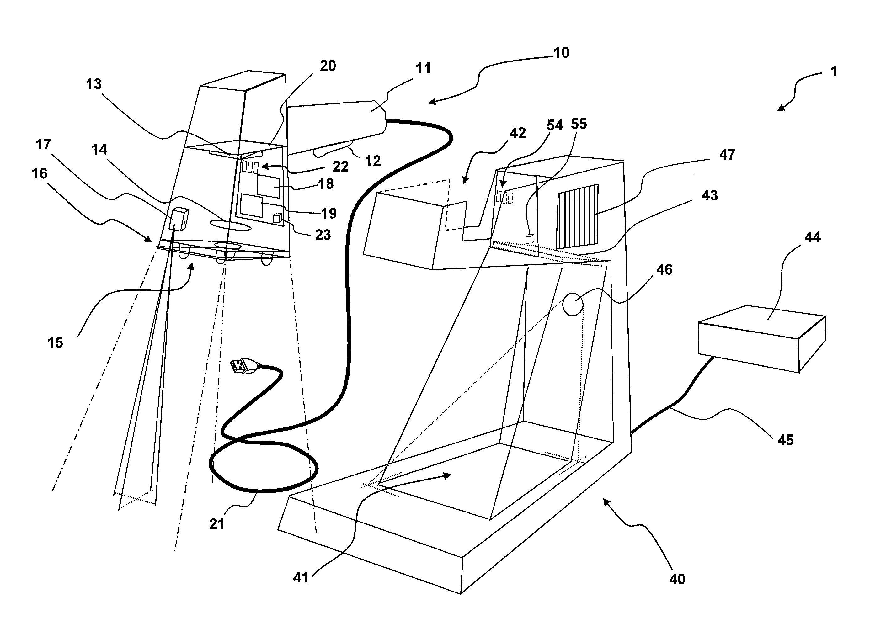
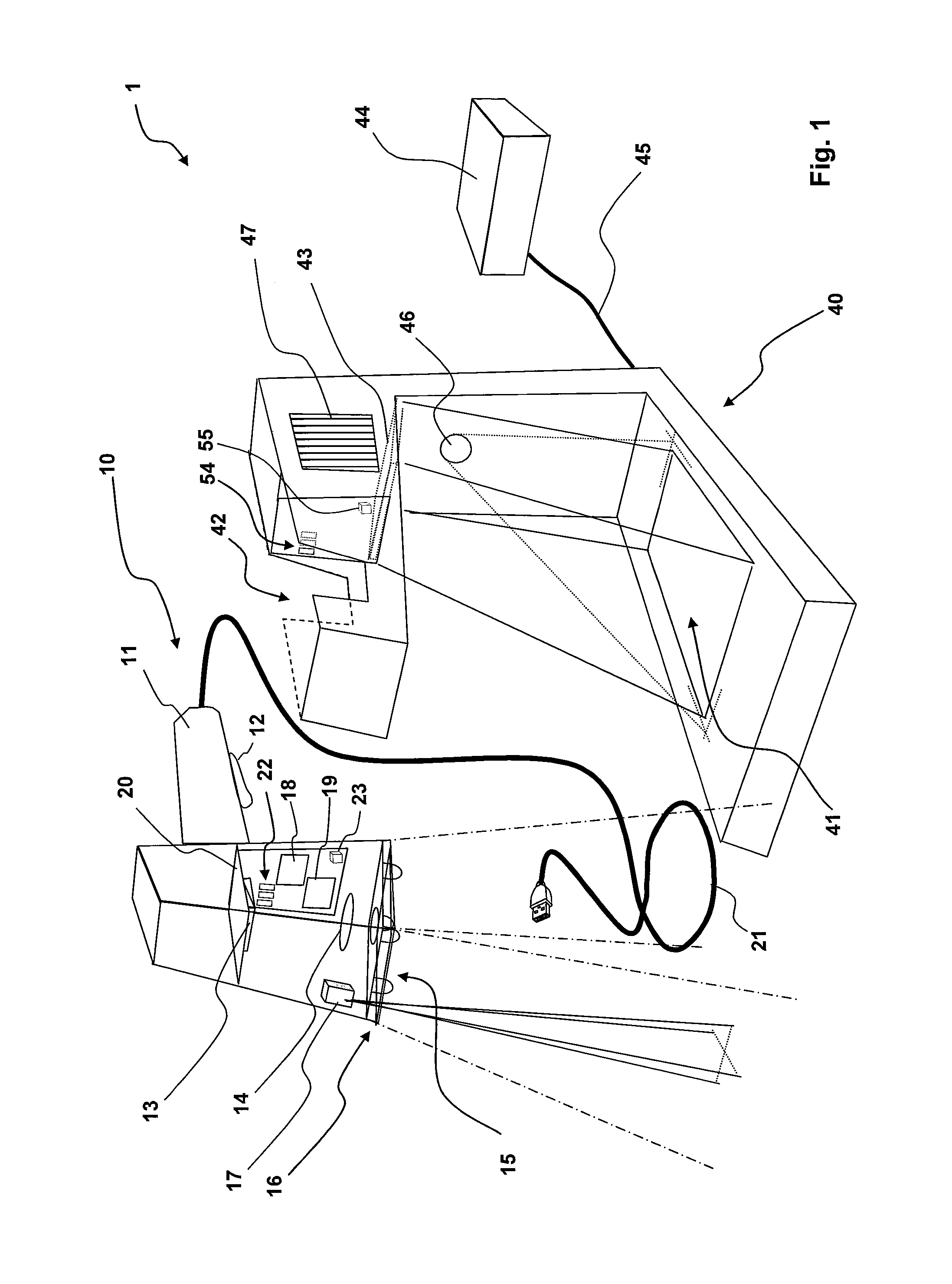
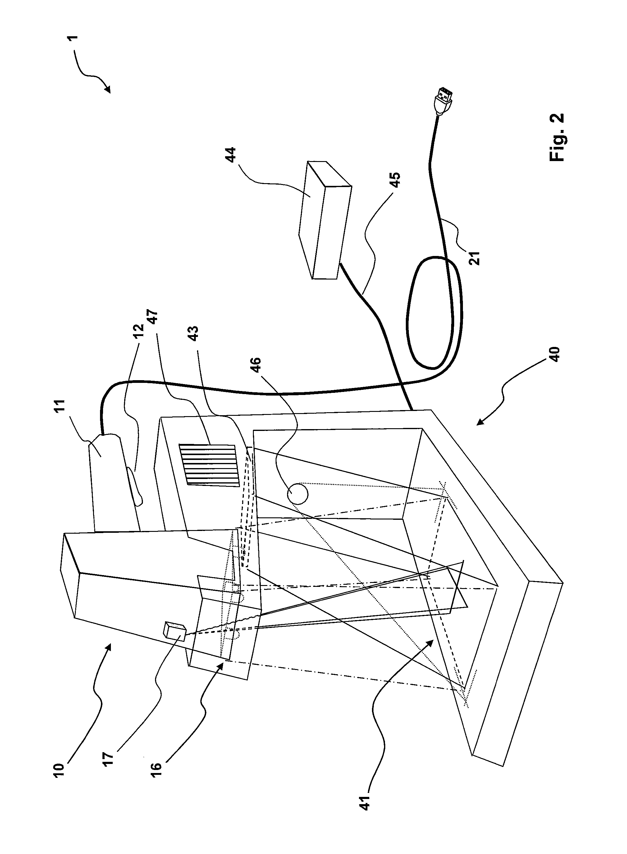
[0070]An embodiment of an apparatus 1 for presentation reading with removable reader according to the invention is shown schematically in FIGS. 1 and 2, wherein in FIG. 2 some components have been left out for the sake of clarity.

[0071]The apparatus 1 comprises a reader 10 and a stand 40 configured to house the reader 10 facing a predetermined reading zone 41.

[0072]In FIG. 1 the reader 10 is removed from the stand 40, while in FIG. 2 the reader 10 is seated in the stand 40.

[0073]The reader 10 shown is gun-shaped, having a handle or grip 11, provided with a trigger activation button 12 that however could also be absent, and with possible other control buttons (not shown).

[0074]The reader 10 comprises a sensor 13, two-dimensional in the case shown, but that could also be one-dimensional, coupled with a receiving optics 14, which could also be absent, facing a light input and output window 15.

[0075]The sensor 13 is configured to detect the light emitted, typically by reflection and / or ...


PUM


Abstract

An apparatus for presentation reading of optical information with removable reader includes an optical information reader and a cradle or stand having a seat for seating the reader facing a predetermined optical information reading zone. The reader has an illuminator and the stand has an illuminator. A processor is configured to control a capture of an image of at least one portion of the reading zone, to analyze the image and, based on the analysis, to drive the switching on of either of the illuminator of the reader and / or the illuminator of the stand. The stand includes an optical component at the illuminator of the reader and / or at an aimer of the reader when seated in the seat, to define an aiming pattern and / or to modify the features of the illuminating beam of the reader.

Description

BACKGROUND AND SUMMARY OF THE INVENTION[0001]The present invention relates to an optical information reading apparatus, more specifically to an apparatus for presentation reading of optical information with removable reader.[0002]In the present description and in the attached claims, the expression “optical information” is used in a broad sense to cover both one-dimensional, stacked and two-dimensional optical codes, wherein information is encoded in the shapes, size, colours and / or mutual positions of elements of at least two distinct colours, and alphanumeric characters, signatures, logos, stamps, trademarks, labels, hand-written text and images in general, and their combinations, in particular present on pre-printed forms, and images containing features suitable for identifying and / or selecting an object based on its shape and / or volume.[0003]In the present description and in the attached claims, the term “light” is used in a broad sense, indicating electromagnetic radiation of a...

Claims


Application Information

Patent Timeline
Patent Type & Authority Patents(United States)
IPC IPC(8): G06K7/10
CPCG06K7/10732G06K7/109G06K7/10752G06K2207/1011G06K2207/1018
Inventor MAZZONE, CLAUDIOCANINI, FEDERICOPARESCHI, FABRIZIOOLIVA, GUIDO, MAURIZIO
Owner DATALOGIC IP TECH
Learn More