Multi-antenna device and communication device

a communication device and multi-antenna technology, applied in the direction of antenna earthing, antenna details, antennas, etc., can solve the problems of difficult to maintain broadband performance, difficult to obtain performance for reducing cross coupling outside of specific frequency, etc., and achieve the effect of maintaining broadband performance and reducing cross coupling between antennas

Inactive Publication Date: 2016-04-05
FUNAI ELECTRIC CO LTD
View PDF10 Cites 3 Cited by
  • Summary
  • Abstract
  • Description
  • Claims
  • Application Information

AI Technical Summary

Benefits of technology

[0008]One object of the present disclosure is to provide a multi-antenna device with which broadband performance can be maintained while cross coupling between antennas is reduced. Another object of the present disclosure is to provide a communication device including such a multi-antenna device.

Problems solved by technology

However, although it is possible to reduce cross coupling between the two antennas at a specific frequency with the multi-mode antenna structure (multi-antenna device) in Patent Literature 1, it has been discovered that there connector elements have frequency characteristics that make it difficult to obtain performance for reducing cross coupling outside of the specific frequency.
Thus, when the two antennas are compatible with a wide frequency band, it is difficult to maintain broadband performance while still reducing cross coupling between the two antennas over the entire corresponding frequency band.

Method used


Image

  • Multi-antenna device and communication device
  • Multi-antenna device and communication device
  • Multi-antenna device and communication device

Examples


first embodiment

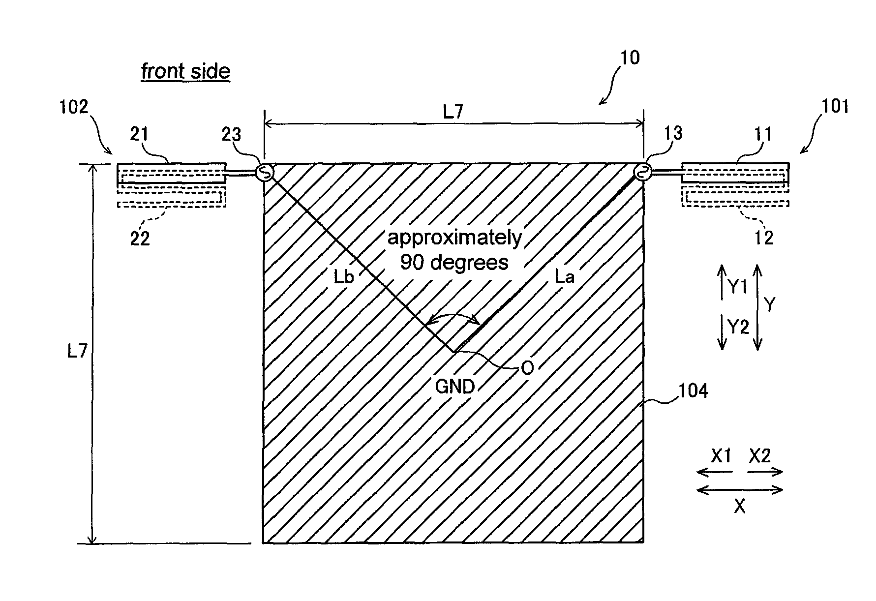
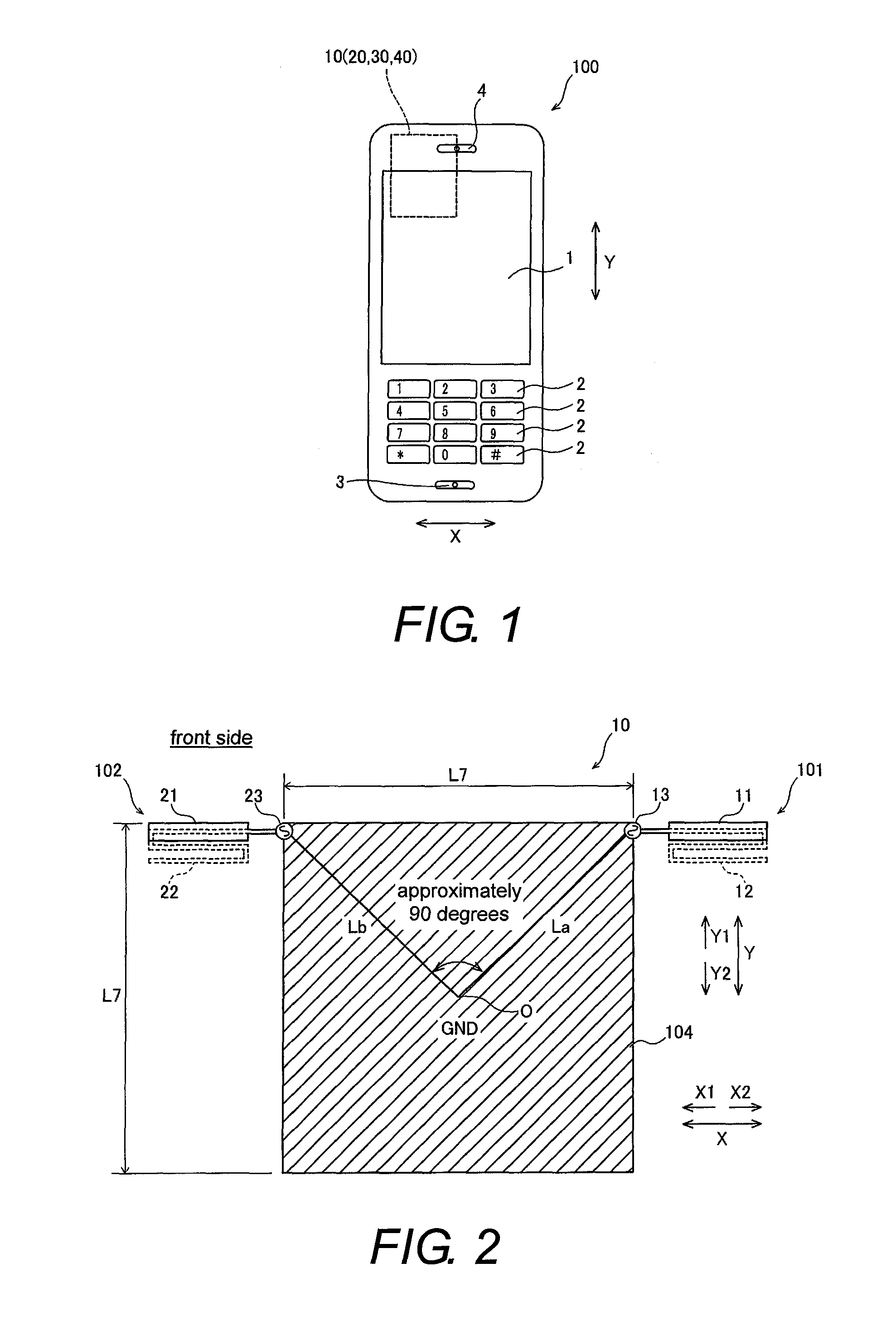
[0032]Referring initially to FIGS. 1 to 6, a portable telephone 100 is illustrated in accordance with a first embodiment. The portable telephone 100 is an example of the “communication device” of the present invention.

[0033]As shown in FIG. 1, the portable telephone 100 pertaining to the first embodiment has a substantially rectangular shape when viewed from the front. The portable telephone 100 includes a display screen component 1, an interface component 2 having number buttons or the like, a microphone 3, and a speaker 4. A multi-antenna device 10 is provided inside the housing of the portable telephone 100.

[0034]The multi-antenna device 10 is configured for use in MIMO (multiple-input and multiple-output) communication that allows multiplexed input and output using a plurality of antennas. The multi-antenna device 10 is compatible with ultra wide band (a band in which the ratio between the maximum and minimum usable frequencies is at least about 1.5 times), so as to be compatibl...

second embodiment

[0069]Next, a multi-antenna device 20 pertaining to a second embodiment will be described through reference to FIG. 9. In this second embodiment, the configuration differs from that in the first embodiment above in that a first grounding plate 204 and a second grounding plate 205 are formed in a circular shape. In view of the similarity between the first and second embodiments, the parts of the second embodiment that are structurally or functionally identical to the parts of the first embodiment will be given the same reference numerals as the parts of the first embodiment.

[0070]As shown in FIG. 9, the first grounding plate 204 of the multi-antenna device 20 pertaining to the second embodiment is formed in a circular shape in plan view, and has a shape that is in point symmetry with the center O of the first grounding plate 204. The second grounding plate 205 is formed in the same shape as the first grounding plate 204, and is disposed so as to overlap with the first grounding plate...

third embodiment

[0074]Next, a multi-antenna device 30 pertaining to a third embodiment will be described through reference to FIG. 10. In this third embodiment, the configuration differs from that in the first embodiment above in that a first grounding plate 304 and a second grounding plate 305 are formed in a regular octagonal shape. In view of the similarity between the first and third embodiments, the parts of the third embodiment that are structurally or functionally identical to the parts of the first embodiment will be given the same reference numerals as the parts of the first embodiment.

[0075]As shown in FIG. 10, the first grounding plate 304 of the multi-antenna device 30 pertaining to the third embodiment is formed in a regular octagonal shape in plan view, and has a shape that is in point symmetry with the center O of the first grounding plate 304. The second grounding plate 305 is formed in the same shape as the first grounding plate 304, and is disposed so as to overlap with the first ...


PUM


Abstract

A multi-antenna device includes a grounding plate, a first antenna and a second antenna. The first antenna includes a first feed element that is grounded to the grounding plate via a first feed point. The second antenna includes a second feed element that is grounded to the grounding plate via a second feed point. The first feed point and the second feed point are disposed such that a straight line connecting the first feed point and a center of the grounding plate and a straight line connecting the second feed point and the center of the grounding plate are substantially perpendicular to each other in a plan view.

Description

CROSS-REFERENCE TO RELATED APPLICATIONS[0001]This application claims priority to Japanese Patent Application No. 2012-254225 filed on Nov. 20, 2012. The entire disclosure of Japanese Patent Application No. 2012-254225 is hereby incorporated herein by reference.BACKGROUND[0002]1. Field of the Invention[0003]The present invention generally relates to a multi-antenna device and a communication device. More specifically, the present invention relates to a multi-antenna device and a communication device having a plurality of antennas.[0004]2. Background Information[0005]A multi-antenna device equipped with a plurality of antennas was known in the past (see Japanese Unexamined Patent Application Publication (Translation of PCT Application) No. JP2010-525680 (Patent Literature 1), for example).[0006]The above-mentioned Patent Literature 1 discloses a multi-mode antenna structure (multi-antenna device) with which a connector element is provided for electrically connecting two antennas toget...

Claims


Application Information

Patent Timeline
Patent Type & Authority Patents(United States)
IPC IPC(8): H01Q1/24H01Q21/00H01Q1/52
CPCH01Q1/521H01Q1/243H01Q1/48
Inventor MIYAKE, YASUNARI
Owner FUNAI ELECTRIC CO LTD
Why Eureka
Try Eureka