Supercharge Your Innovation With Domain-Expert AI Agents!

Display device in which feature data are exchanged between drivers

a technology of display device and driver, which is applied in the direction of static indicating devices, instruments, etc., can solve the problems of increased power consumption, deterioration of display quality, and possible problem of the necessary and achieve the effect of reducing the data transmission rate and cos

Active Publication Date: 2016-04-12
SYNAPTICS JAPAN GK
View PDF10 Cites 2 Cited by
  • Summary
  • Abstract
  • Description
  • Claims
  • Application Information

AI Technical Summary

Benefits of technology

[0009]Therefore, an objective of the present invention is to provide a display device which incorporates a plurality of drivers to drive a display panel, in which an appropriate correction calculation is performed on input image data with a reduced data transmission rate and cost.

Problems solved by technology

The recent increase in the panel size and resolution of LCD (liquid crystal display) panels has caused a problem of the increase in the power consumption.
However, the decrease in the brightness of the backlight undesirably causes a problem that the display quality is deteriorated due to the insufficient contrast for images with reduced brightness.
According to a study of the inventors, a problem related to the necessary data transmission rate and cost may occur, when the technique for performing a correction calculation on the input image data is applied to a display device which includes a plurality of display panel drivers to drive a display panel.

Method used


Image

  • Display device in which feature data are exchanged between drivers
  • Display device in which feature data are exchanged between drivers
  • Display device in which feature data are exchanged between drivers

Examples


first embodiment

(First Embodiment)

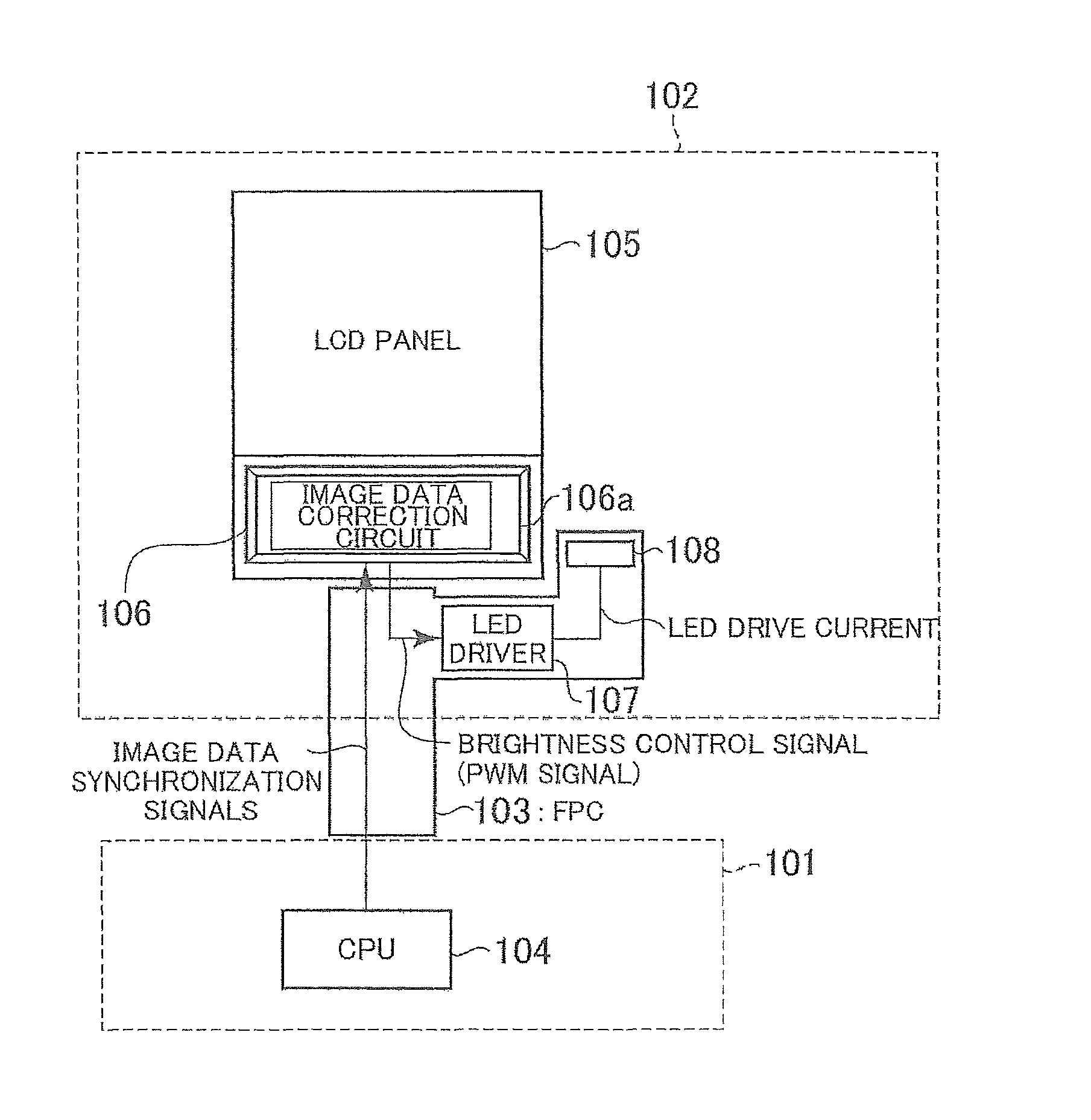
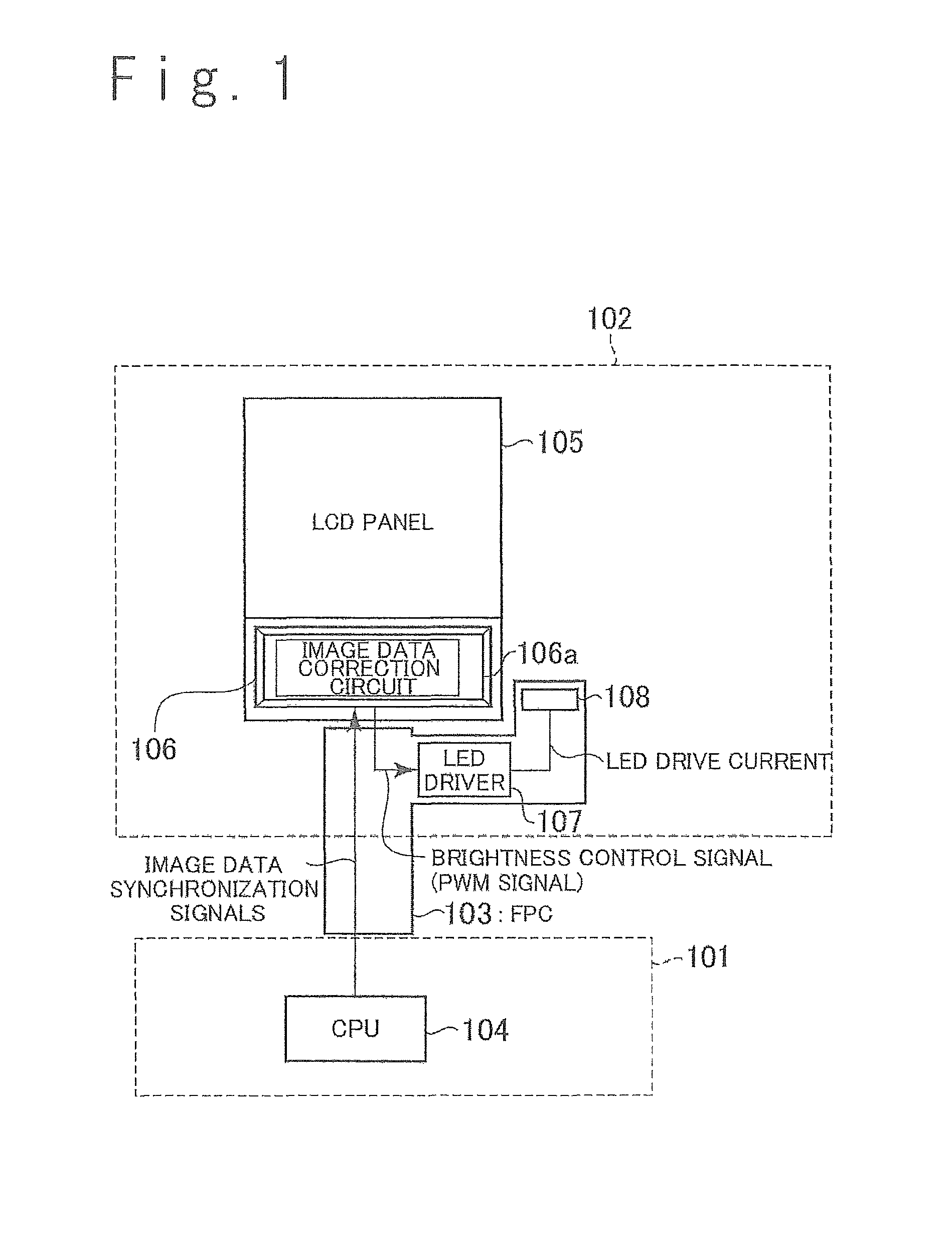
[0062]FIG. 4 is the block diagram illustrating an exemplary configuration of a display device in a first embodiment of the present invention. The display device in FIG. 1 is configured as a liquid crystal display device and includes a main block 1, a liquid crystal display block 2 and FPCs 3-1 and 3-2. The main block 1 includes a CPU 4 and the liquid crystal display block 2 includes an LCD panel 5. The main block 1 and the liquid crystal display block 2 are coupled by the FPCs 3-1 and 3-2.

[0063]In the LCD panel 5, a plurality of data lines and a plurality of gate lines are laid, and pixels are arranged in a matrix. In this embodiment, pixels are arranged in V rows and H columns in the LCD panel 5. In this embodiment, each pixel includes a subpixel associated with red (hereinafter, referred to as R subpixel), a subpixel associated with green (hereinafter, referred to as G subpixel) and a subpixel associated with blue (hereinafter, referred to as B subpixel). This im...

second embodiment

(Second Embodiment)

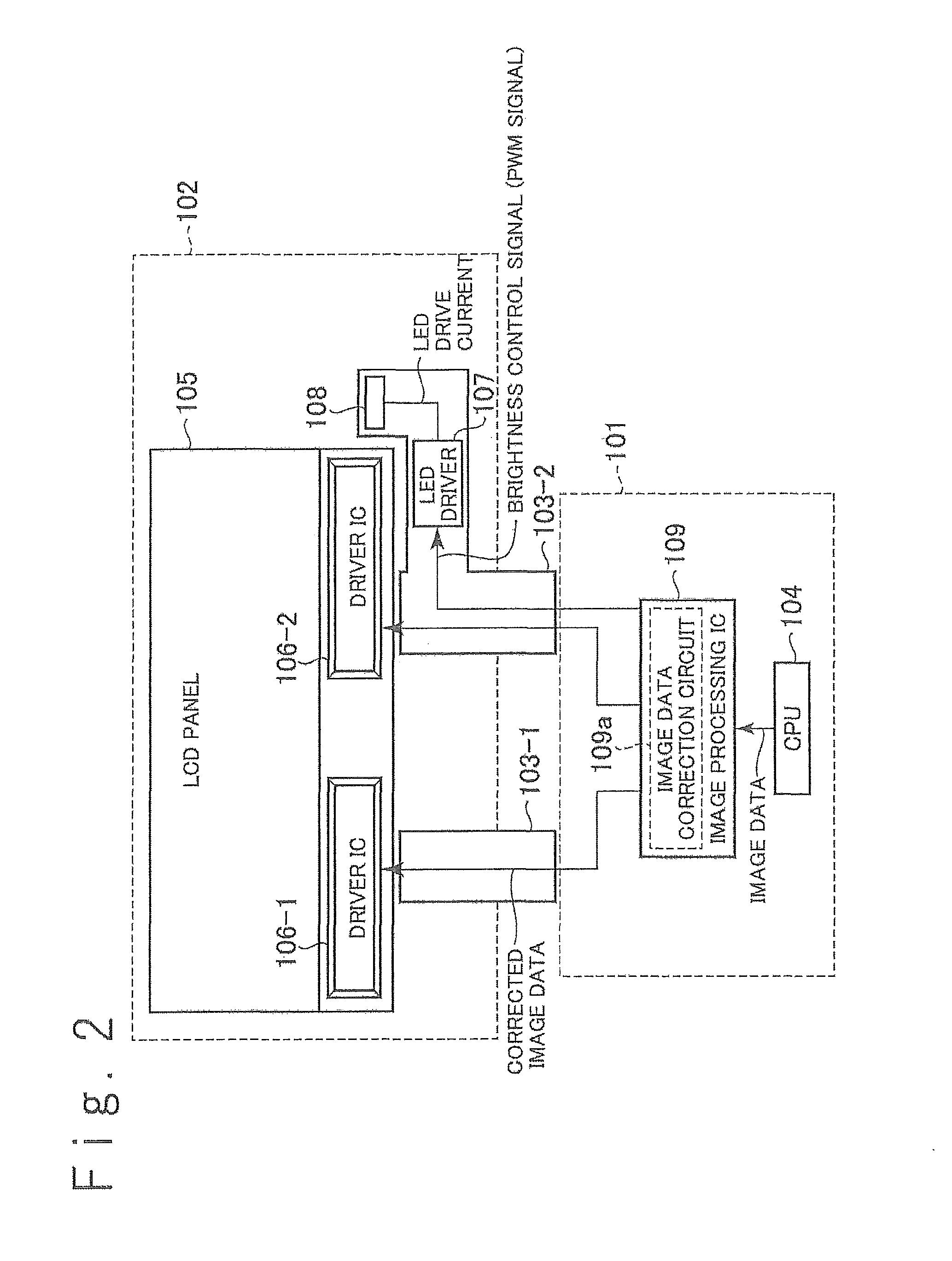
[0258]FIG. 21 is a block diagram illustrating an exemplary configuration of a liquid crystal display device in a second embodiment of the present invention. In the second embodiment, as is the case with the first embodiment, the LCD panel 5 is driven by two driver ICs 6-1 and 6-2. Although the configuration of the driver ICs 6-1 and 6-2 in the second embodiment is substantially the same as the first embodiment, the second embodiment differs from the first embodiment in the operation for unifying the correction calculations in the driver ICs 6-1 and 6-2 (namely, the operation for instructing the driver ICs 6-1 and 6-2 to perform the same correction calculation).

[0259]In the second embodiment, one of the driver ICs 6-1 and 6-2 is operated as a master driver, and the other is operated as a slave driver. Here, the master driver is a driver which controls the operation for unifying the correction calculations in the driver ICs 6-1 and 6-2. The slave driver is a driver ...


PUM


Abstract

A display device includes a display panel including a display region and first and second drivers. Feature data indicating feature values of first and second images displayed on first and second portions of the display region are exchanged between the first and second drivers, and the first and second drivers drive the first and second portions of the display region in response to the feature data.

Description

CROSS REFERENCE[0001]This application claims priority of Japanese Patent Application No. Japanese Patent Application No. 2012-269721, filed on Dec. 10, 2012, the disclosure which is incorporated herein by reference.TECHNICAL FIELD[0002]The present invention relates to a display device, a display panel driver, and an operating method of a display device, in particular, to a panel display device configured to drive a display panel by using a plurality of display panel drivers, and a display panel driver and the operating method which are applied to the display device.BACKGROUND ART[0003]The recent increase in the panel size and resolution of LCD (liquid crystal display) panels has caused a problem of the increase in the power consumption. One approach for suppressing the power consumption is to decrease the brightness of the backlight. However, the decrease in the brightness of the backlight undesirably causes a problem that the display quality is deteriorated due to the insufficient ...

Claims


Application Information

Patent Timeline
Patent Type & Authority Patents(United States)
IPC IPC(8): G09G3/34G09G3/36
CPCG09G3/3406G09G3/3685G09G2320/064G09G2320/0646G09G2360/16
Inventor NOSE, TAKASHIFURIHATA, HIROBUMISUGIYAMA, AKIOMIZUNO, TOSHIO
Owner SYNAPTICS JAPAN GK
Features
  • R&D
  • Intellectual Property
  • Life Sciences
  • Materials
  • Tech Scout
  • Unparalleled Data Quality
  • Higher Quality Content
  • 60% Fewer Hallucinations
Learn More