Imprint method, and imprint apparatus for implementing the same

a technology of imprinting and printing method, which is applied in the direction of photomechanical equipment, instruments, nanoinformatics, etc., can solve the problems of inconvenient deposition of resin, risk of mold breakdown, and heavy deposition and breakdown risk, and achieve the effect of less peeling for

Active Publication Date: 2016-04-19
DAI NIPPON PRINTING CO LTD
View PDF4 Cites 1 Cited by
  • Summary
  • Abstract
  • Description
  • Claims
  • Application Information

AI Technical Summary

Benefits of technology

[0028]The inventive imprint method includes, and is comprised of, a resin layer formation step of interposing a material or material layer to be transferred between a surface of a mold having a concavo-convex structure region and an imprinting substrate to form the material layer to be transferred with a concavo-convex structure pattern, and a peeling step of peeling said mold off the resin layer, wherein the peeling step comprises a region-of-contact recognition operation of recognizing and determining a region of contact of the mold with the material layer to be transferred, a center-of-gravity locating operation of determining a center of gravity of the morphology of the thus recognized region of contact on the basis of said morphology, and a peeling operation of determining a point of force for applying peeling force to the mold or imprinting substrate on the basis of the determined center of gravity, thereby acting the peeling force on the point of force. The arrangement being like this, it is possible to implement peeling with much less peeling force depending on the morphology of the material or material layer to be transferred, thereby avoiding the occurrence of inconvenient deposition onto the mold of the material or material layer to be transferred.

Problems solved by technology

In general, a risk of inconvenient deposition of the resin that is the material to be transferred onto the mold, and a risk of mold breakdowns has correlations with the peeling force necessary for peeling: it would appear to be that the stronger the peeling force, the heavier the risks of deposition and breakdowns are.
However, although the method of providing the releasing layer on the concavo-convex surface of the mold is very effective for where the area of contact of the mold with the resin layer is limited, it is to be understood that when the area of contact grows large for the purposes of boosted-up productivity or the like, the force necessary for peeling grows much stronger, so the simple provision of the releasing layer would be far away from the solution of a problem with peeling.
Further, the prior art does not teach anything specific about any possible method that enables peeling with much less peeling force so as to avoid the occurrence of inconvenient deposition onto the mold of the resin that is the material to be transferred.

Method used


Image

  • Imprint method, and imprint apparatus for implementing the same
  • Imprint method, and imprint apparatus for implementing the same
  • Imprint method, and imprint apparatus for implementing the same

Examples


example 1

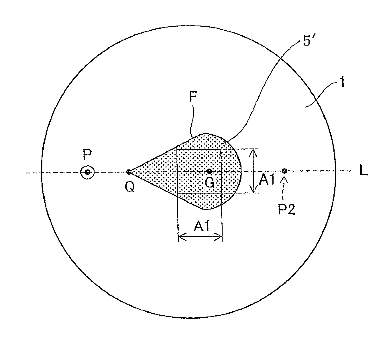
[0123]A region of contact (resin layer 5′) similar to such morphologies as depicted in FIGS. 3A and 38 was prepared. Unlike FIG. 3A, however, the region of contact is of morphology capable of approximating to a rectangle. Suppose now that the teardrop in FIG. 3A takes on a rectangular morphology.

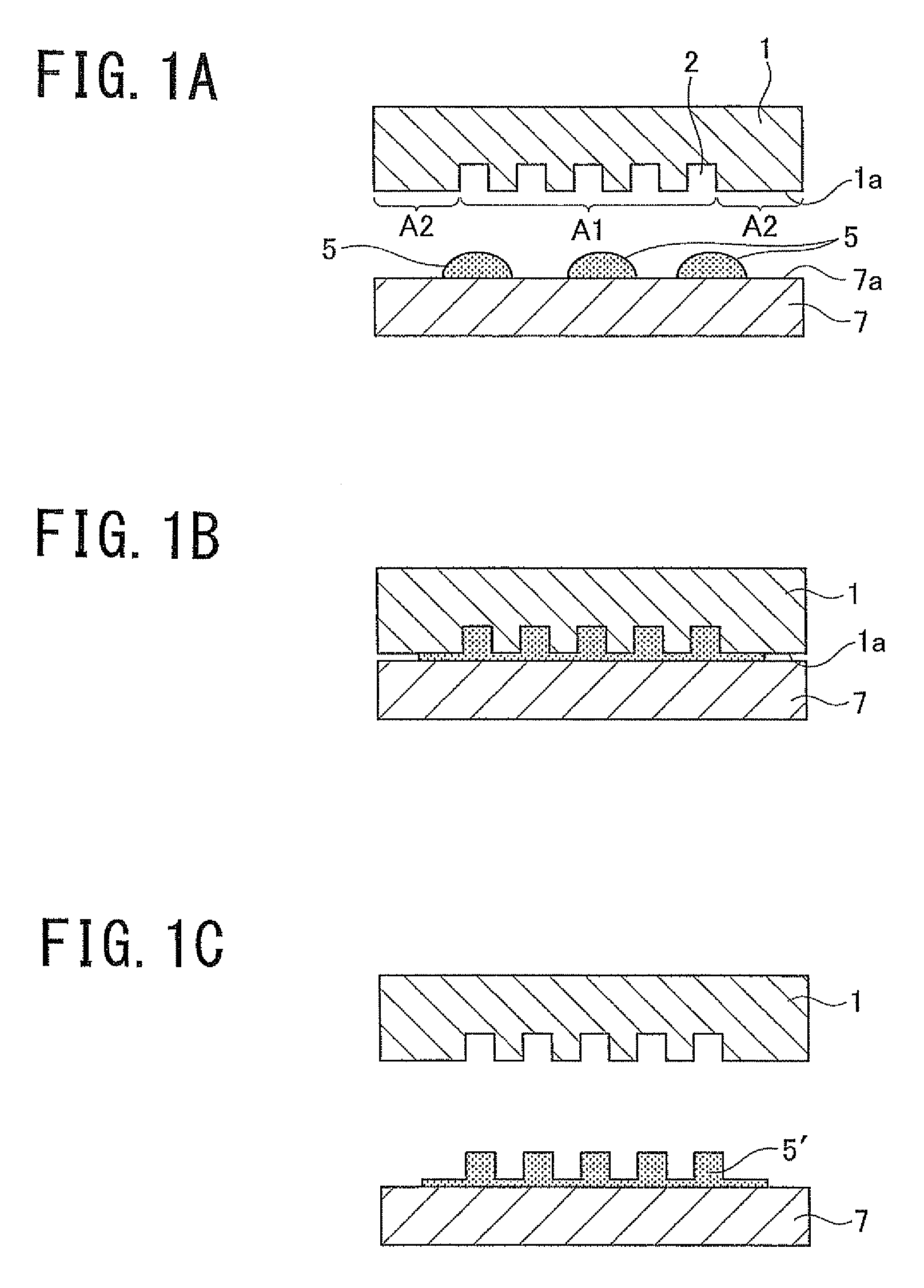
[0124]Quartz glass having a surface size of 40×40 mm and a thickness of 6.35 mm was used to prepare a mold. A pattern depth of 50 nm and a line width / space of 50 nm / 50 nm were repeated 100 times into a length of 2 mm. Four such patterns were provided, one at the center of the mold, and three 5 mm away from the center in the XY direction. In short, the concavo-convex structure region A1 may be taken as a rectangle of 10.02 mm×14 mm at the center of the mold surface.

[0125]The mold surface was coated with a releasing agent Optool DSX (Daikin Industries, Ltd.).

[0126]A silicon substrate of 0.625 mm in thickness was provided as an imprinting substrate.

[0127]A photo-curing resin material having the...


PUM

PropertyMeasurementUnit
internal angleaaaaaaaaaa
thicknessaaaaaaaaaa

Abstract

An imprint method includes, in the peeling step of peeling a mold off the material layer to be transferred, a region-of-contact recognition operation of recognizing and determining a region of contact of the mold with the material layer to be transferred, a center-of-gravity locating operation of determining a center of gravity of a morphology of the thus recognized region of contact on the basis of that morphology, and a peeling operation of determining a point of force for applying peeling force to the mold or the imprinting substrate in relation to the center of gravity determined by the center-of-gravity locating operation, thereby acting the peeling force on the point of force.

Description

BACKGROUND OF THE INVENTION[0001]1. Field of the Invention[0002]The present invention relates to an imprint method and an imprint apparatus for transferring and forming a desired pattern (such as lines, and graphic patterns) on the material to be transferred.[0003]2. Description of the Related Art[0004]Attentions have now been focused on imprint methods that are a sort of micro-machining or micro-processing technologies. A typical imprint method is a pattern-formation technique that uses a mold member having a minute concavo-convex structure formed on a substrate surface to transfer that concavo-convex structure to the material to be transferred, thereby achieving full-size transfer of that concavo-convex structure.[0005]For such imprint methods, for instance, there has been a photo-imprint method or a thermal imprint method known in the art. In the photo-imprint method, for instance, a photo-curing resin layer having fluidity is located as the material to be transferred on a substr...

Claims


Application Information

Patent Timeline
Patent Type & Authority Patents(United States)
IPC IPC(8): B05D3/12G03F7/00B05C11/00B82Y10/00B82Y40/00B05D3/06B05D1/42B29C33/62G03F7/004G03F7/027
CPCG03F7/0002B82Y10/00B82Y40/00B05C11/00B05D1/42B05D3/067B05D3/12B29C33/62G03F7/0046G03F7/027B29C43/58B29C2043/5833
Inventor ARITSUKA, YUKINAKATA, NAOKO
Owner DAI NIPPON PRINTING CO LTD
Why Eureka
Try Eureka