Sterile surgical headlight aperture adjusting device

a technology of aperture adjustment and sterile surgical headlights, which is applied in the field of sterile surgical headlight aperture adjustment devices, can solve the problems of inability to personally manipulate non-sterile components, ineffective procedures, and inability to fully utilize aperture adjustment components for their intended purpos

Inactive Publication Date: 2016-05-03
SURGIRIGHT
View PDF12 Cites 16 Cited by
  • Summary
  • Abstract
  • Description
  • Claims
  • Application Information

AI Technical Summary

Benefits of technology

[0004]The present invention relates to medical devices, and more specifically, the present invention relates to a medical device that allows a surgeon to personally adjust the aperture of the light beam being projected from his or her surgical headlight during surgery, as often as necessary, and without compromising the sterile field.
[0005]In various embodiments, the medical device comprises a sterile, disposable, single-use aperture adjusting device comprising a handle having a proximate end and an operation portion at its distal end; wherein said operation portion is specifically engineered to engage and hold by friction an aperture adjusting component positioned on a surgical headlight assembly; wherein the handle serves to facilitate the engagement of the device to the aperture adjusting component; wherein engagement of said aperture adjusting device to said aperture adjusting component allows a user to use said handle to manipulate the aperture adjusting component, thereby adjusting the aperture of the light beam being projected from said headlight during surgery. Because the handle of the aperture adjusting device is sterile, the surgeon can manipulate the handle as often as necessary, without the assistance of others, and without compromising the sterile field.
[0006]According to one embodiment of the invention, the aperture adjusting component of the surgical headlight assembly comprises an aperture adjusting dial, and the sterile aperture adjusting device comprises a thin rod-shaped handle having a proximate end and having an operation portion comprising a U-shaped collar at its distal end. The U-shaped collar's interior is specifically engineered to engage the outside surface of the aperture adjusting dial, thus allowing for the aperture adjusting device to engage and hold by friction the aperture adjusting dial. The engagement of the device to the dial is facilitated by use of the sterile handle and then allows the user to use the sterile handle to manipulate the dial to adjust the aperture of the light beam being projected from the surgical headlight as often as necessary during surgery, without compromising the sterile field.
[0007]According to a further aspect of the present invention, a method of adjusting the aperture of the light beam being projected from a surgical headlight assembly secured to the head of a surgeon during surgery is provided. The method includes: removal of a sterile aperture adjusting device of the invention from its packaging by a medical professional or surgeons assistant in the sterile field, without compromising its sterility; use of the handle of said aperture adjusting device by the surgeon to engage said device to an aperture adjusting component positioned on said surgical headlight assembly; and use of said handle by the surgeon to manipulate said adjusting component to adjust the aperture of the projected light beam during surgery as often as necessary, without compromising the sterile field. After the surgical procedure has been completed, the aperture adjusting device is disengaged from the aperture dial by the surgeon (or other personnel) using the handle of the device to pull the device away from the headlight assembly using gentle force. The aperture adjusting device can then be properly disposed as medical waste.

Problems solved by technology

Unfortunately, these aperture adjusting components cannot be fully utilized for their intended purpose due to lack of sterility and associated risk factors.
As such, the surgeon typically adjusts the aperture adjusting component to a particular setting prior to entering the sterile field and then is unable to personally manipulate the non-sterile component to re-adjust the aperture after entering the sterile field because he or she would compromise the sterile field.
Clearly, such procedures are not efficient, slow down the operation, and introduce an unnecessary sterility risk factor.
This limitation discourages the surgeon from adjusting the aperture in situations where he or she might otherwise have done so but for the inconvenience and risk.

Method used


Image

  • Sterile surgical headlight aperture adjusting device
  • Sterile surgical headlight aperture adjusting device
  • Sterile surgical headlight aperture adjusting device

Examples


Embodiment Construction

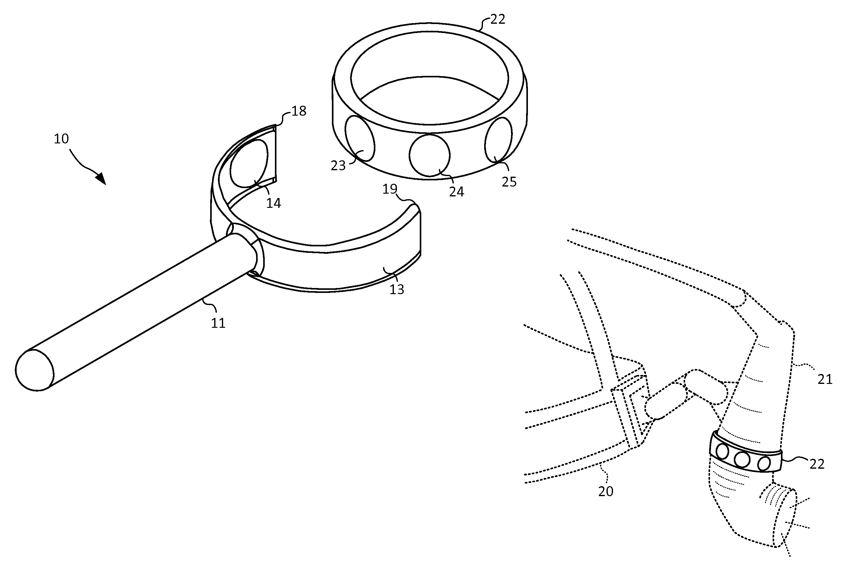
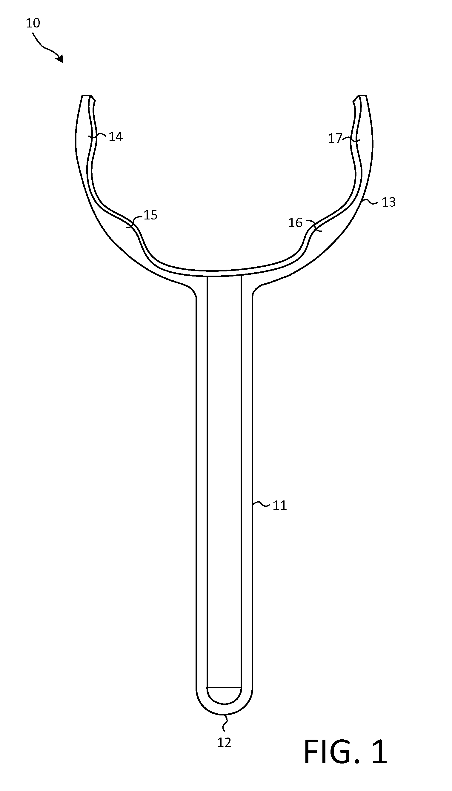
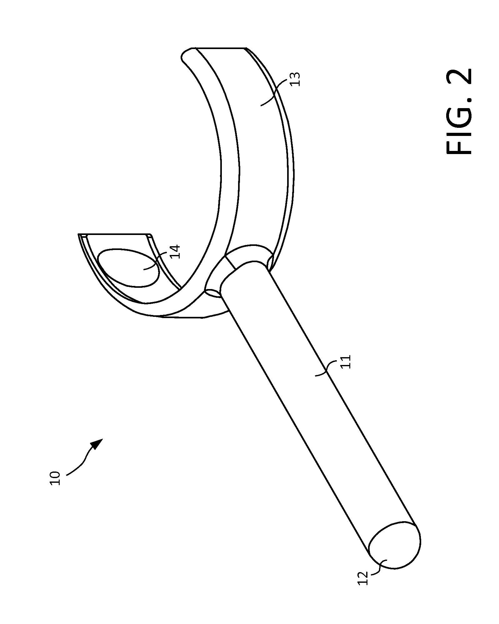
[0014]Importantly, the aperture adjusting devices of the invention will be manufactured using a material that possesses two key properties: 1) a material that can be sterilized using FDA approved sterilization techniques; and 2) a material that possesses excellent memory properties (“resiliency”) allowing it to temporarily expand and contract back to its original shape, such that it can engage and hold by friction the aperture adjusting component, and then be disengaged from said component by gentle force. Any plastic or metal material possessing such properties can be used in the manufacturing of the aperture adjusting devices of the invention. Many such modern plastics and / or metals are well known to those of ordinary skill in the art. The aperture adjusting devices of the invention can be manufactured as a one piece device or as multiple components which are assembled just prior to use. Methods of manufacturing the devices of the present invention are well known and understood by...


PUM


Abstract

The present invention relates to medical devices, and more specifically, the present invention relates to a medical device that allows a surgeon to personally adjust the aperture of the light beam being projected from his or her surgical headlight during surgery, as often as necessary and without compromising the sterile field.

Description

BACKGROUND OF THE INVENTION[0001]The use of surgical headlights to provide a spotlight beam of intense light coincident with the wearer's line of sight, independent from overhead and / or ambient lighting, is well established in the art. Surgical headlight systems typically include a headlight assembly mounted to a surgical headgear at the wearer's forehead at a location approximately between the wearer's eyes. A typical headlight assembly comprises an assembly of optic elements and a light source (xenon or halogen) and can receive an emitting end of a fiber optic cable and then focus and direct the light from the cable into a beam aimed forward of the wearer. Alternatively, the headlight assembly may comprise an LED (light emitting diode) mounted in its housing and used as the light source. The LED light source is connected by a cable to a power supply.[0002]Various models of commercially-available surgical headgear comprise a headlight assembly which comprises an aperture adjusting ...

Claims


Application Information

Patent Timeline
Patent Type & Authority Patents(United States)
IPC IPC(8): A61B1/06
CPCA61B90/30A61B90/50A61B2090/502A61B90/35
Inventor ESTWICK, GARETHRIFKIN, RIAN
Owner SURGIRIGHT
Why Eureka
Try Eureka