Photovoltaic frame fastener

a technology of photovoltaic frame and fastener, which is applied in the direction of rod connection, heat collector mounting/support, lighting and heating apparatus, etc., can solve the problems of affecting the quality of photovoltaic frame, so as to reduce assembly costs, manufacture and install fast, and improve quality

Active Publication Date: 2016-05-03
A RAYMOND & CO
View PDF100 Cites 30 Cited by
  • Summary
  • Abstract
  • Description
  • Claims
  • Application Information

AI Technical Summary

Benefits of technology

[0005]The present photovoltaic frame fastener is advantageous over traditional devices. For example, the one-piece nature of the present fastener is inexpensive and fast to manufacture, install and remove. Furthermore, the present fastener is suitable for pre-assembly to the frame offsite or at a manufacturing plant, thereby improving quality and reducing assembly cost. Moreover, the present fastener advantageously hides the snap-in wing sections securing the frame and strut, thereby making theft and vandalism difficult. In an embodiment where a snap-in wing and frame receiving slot are directly below a flexible retaining tongue, the retention forces are direction in-line thereby advantageously reducing torsion on the fastener which achieves a more secure attachment with less stress on the fastener, frame and solar panel, and requiring lower installation force. In the lateral tab embodiment, a more secure attachment is realized by reducing side-to-side and / or front-to-back tilting, while also preventing over-insertion of a fastener into a strut opening. Additional advantages and features of the present invention will become apparent from the following description and appended claims taken in conjunction with the accompanying drawings.BRIEF DESCRIPTION OF THE DRAWINGS
[0052]Referring now to FIGS. 26-29, a third embodiment of a lower removal tool 250 is used to remove a snap-in photovoltaic frame grounding clip 252. Grounding clip 252 includes a pair of spaced apart clamps 254 and 256, an upper bridge 258 and a mounting section 260. Each clamp has a generally C-shape, thereby creating an openly accessible receptacle therebetween. Furthermore, a lead-in wall 262 upwardly and outwardly angles away from each clamp to ease insertion of a flat lateral flange segment of frame 26 therein during assembly. If used for grounding, a pair of pointed barbs 264 internally project from each upper section of clamps 254 and 256. Each barb 264 cuts into and gouges the adjacent surface of frame 26 to scrape off the anodized coating thereat. This provides multiple satisfactory electrical grounding paths between the base material of the frame and the clip. This can be achieved by the simple linear insertion of the clamps of the clip onto the flange of the frame without the need for rotation or a threaded attachment. Alternately, the same fastener clip 252 can be used in a non-electrical grounding manner if barbs 264 are omitted.

Problems solved by technology

These devices, however, have many loose parts, and are time consuming and complex to install on a job site, such as on top of a windy roof, which thereby incurs significant labor expense and effort.
Moreover, the present fastener advantageously hides the snap-in wing sections securing the frame and strut, thereby making theft and vandalism difficult.

Method used


Image

  • Photovoltaic frame fastener
  • Photovoltaic frame fastener
  • Photovoltaic frame fastener

Examples


first embodiment

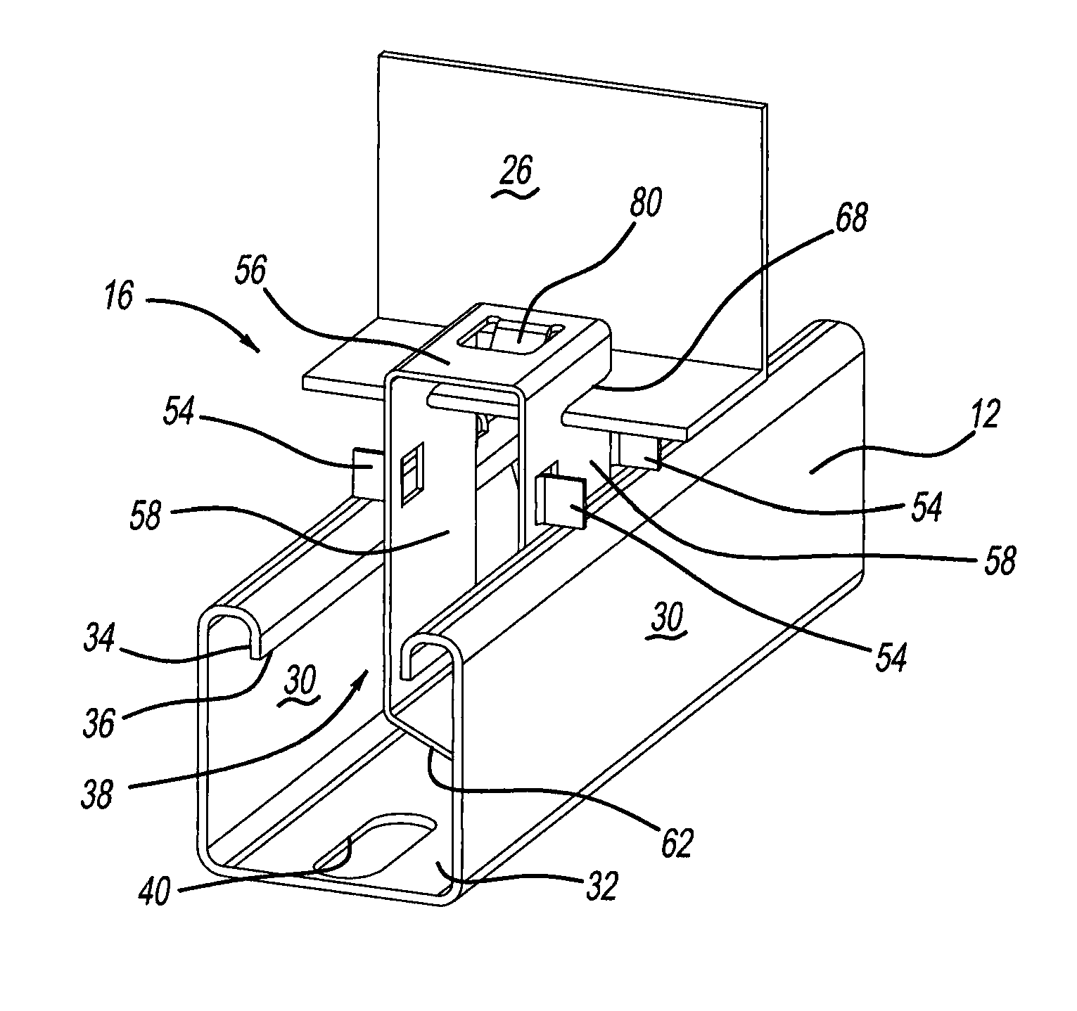
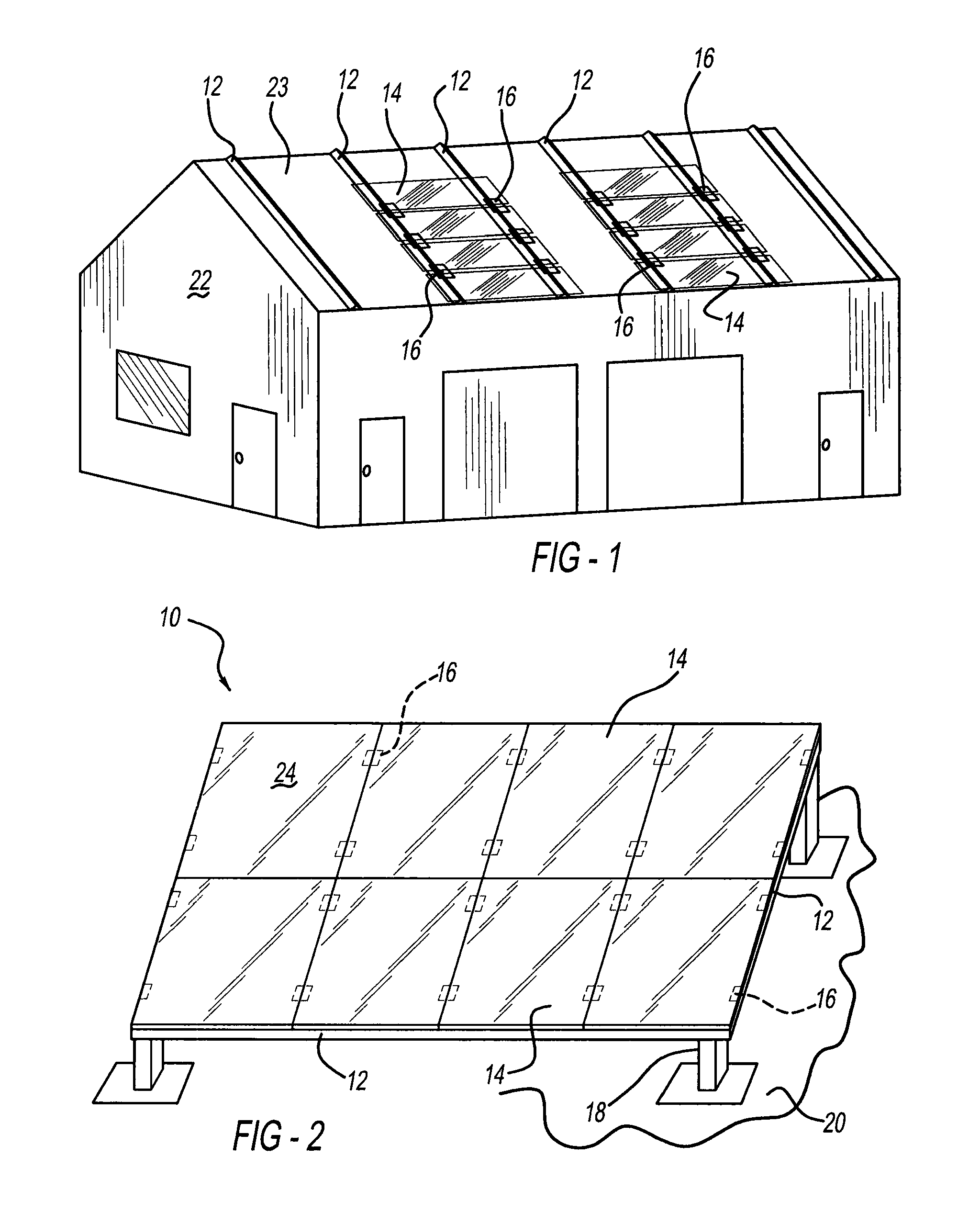
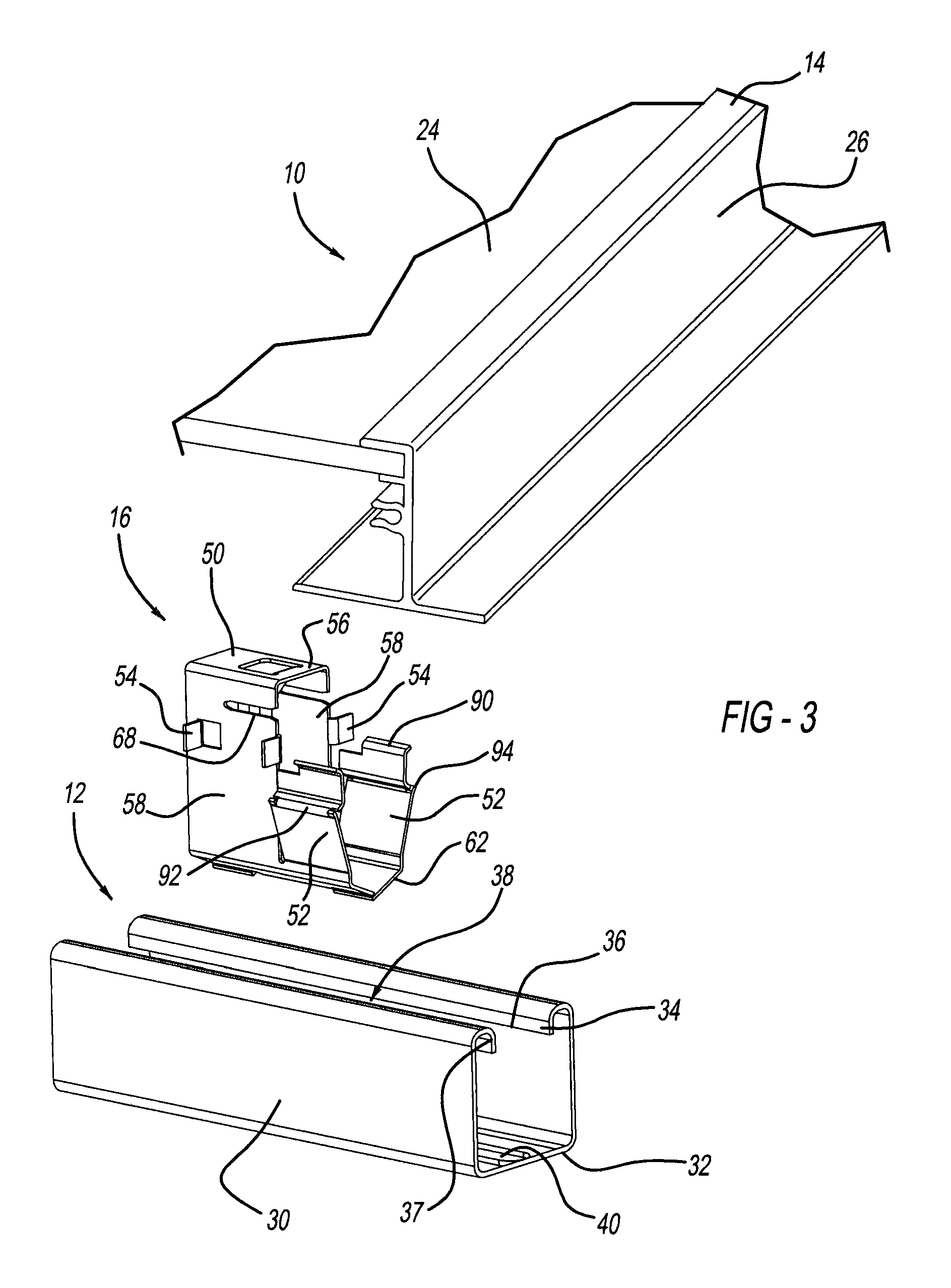
[0036]Referring to FIGS. 1-3, a photovoltaic frame fastener assembly 10 includes elongated and rigid rails or struts 12, solar or photovoltaic panel modules 14, and fasteners 16. Struts 12 are mounted to vertical legs 18 attached to land or ground 20 in one configuration. In another configuration, struts 12 are bolted onto a roof clamp or other structure on a roof or side of a building 22. Each photovoltaic module 14 includes a chemically coated glass photovoltaic panel 24 and an adhesively attached, peripheral metallic frame 26. Glass photovoltaic panel 24 and metallic frame 26 are provided as a pre-assembled unit or may be provided as separate units to the installation site.

[0037]As best shown in FIGS. 3-5 and 8, strut 12 has a uniform and generally U-shaped cross-section as defined by upstanding sidewalls 30 joined by a bottom wall 32. A reverse-turned wall 34 extends from a top end of each sidewall 30 and terminates in a downwardly directed edge 36. Downwardly directed edge 36 p...

third embodiment

[0052]Referring now to FIGS. 26-29, a lower removal tool 250 is used to remove a snap-in photovoltaic frame grounding clip 252. Grounding clip 252 includes a pair of spaced apart clamps 254 and 256, an upper bridge 258 and a mounting section 260. Each clamp has a generally C-shape, thereby creating an openly accessible receptacle therebetween. Furthermore, a lead-in wall 262 upwardly and outwardly angles away from each clamp to ease insertion of a flat lateral flange segment of frame 26 therein during assembly. If used for grounding, a pair of pointed barbs 264 internally project from each upper section of clamps 254 and 256. Each barb 264 cuts into and gouges the adjacent surface of frame 26 to scrape off the anodized coating thereat. This provides multiple satisfactory electrical grounding paths between the base material of the frame and the clip. This can be achieved by the simple linear insertion of the clamps of the clip onto the flange of the frame without the need for rotatio...


PUM


Abstract

A photovoltaic frame fastener is provided. In one aspect, a photovoltaic frame attachment apparatus includes a strut or rail defining a generally U-shaped channel and a snap-in clip or fastener. In another aspect, a single-piece fastener includes a strut-engaging surface, at least one flexible wing matable with an opening in a strut, a flexible tongue internally projecting in a central manner from a top wall of a body, and a slot adapted to receive a portion of a photovoltaic panel frame. Yet another aspect of a photovoltaic frame fastener includes laterally projecting tabs abutting against a top of a strut.

Description

BACKGROUND AND SUMMARY[0001]The present disclosure relates generally to a fastener and more particularly to a photovoltaic frame fastener.[0002]Traditionally, peripheral mounting frames holding solar or photovoltaic panels are mounted to a supporting structure on a building roof or on the land through use of threaded fasteners and multi-piece brackets. Exemplary traditional devices are disclosed in U.S. Pat. No. 7,758,011 entitled “Adjustable Mounting Assembly for Standing Seam Panels” which issued to Haddock on Jul. 20, 2010, and U.S. Pat. No. 6,105,317 entitled “Mounting System For Installing an Array of Solar Battery Modules of a Panel-Like Configuration on a Roof” which issued to Tomiuchi et al. on Aug. 22, 2000. These patents are incorporated by reference herein. These devices, however, have many loose parts, and are time consuming and complex to install on a job site, such as on top of a windy roof, which thereby incurs significant labor expense and effort.[0003]Another solar ...

Claims


Application Information

Patent Timeline
Patent Type & Authority Patents(United States)
IPC IPC(8): H02S20/23F24J2/52F16B7/04F24J2/46
CPCF24J2/5256H02S20/23F16B7/0473F24J2002/4663F24J2002/4665Y02E10/47Y02B10/12Y10T403/54H02S20/00F24S25/634F24S2025/6003F24S2025/6004Y02E10/50Y02B10/10
Inventor CHEUNG, BRIAN C.DUPONT, LUC
Owner A RAYMOND & CO
Why Eureka
Try Eureka