Linear drain having adjustable length

a technology of linear drains and drains, applied in the direction of sewers, water installations, douches, etc., can solve the problems of less reliable, time-consuming, and conventional methods of installation, and achieve the effect of facilitating installation of linear drains

Active Publication Date: 2016-05-10
GOOF PROOF PROD LLC
View PDF6 Cites 37 Cited by
  • Summary
  • Abstract
  • Description
  • Claims
  • Application Information

AI Technical Summary

Benefits of technology

[0027]The primary object of the invention is to advance the art of linear drains by providing a linear drain that incl

Problems solved by technology

It is sometimes advantageous, however, to provide an elongate drain that extends the entire width or length of a shower stall.
Installers o

Method used


Image

  • Linear drain having adjustable length
  • Linear drain having adjustable length
  • Linear drain having adjustable length

Examples


Embodiment Construction

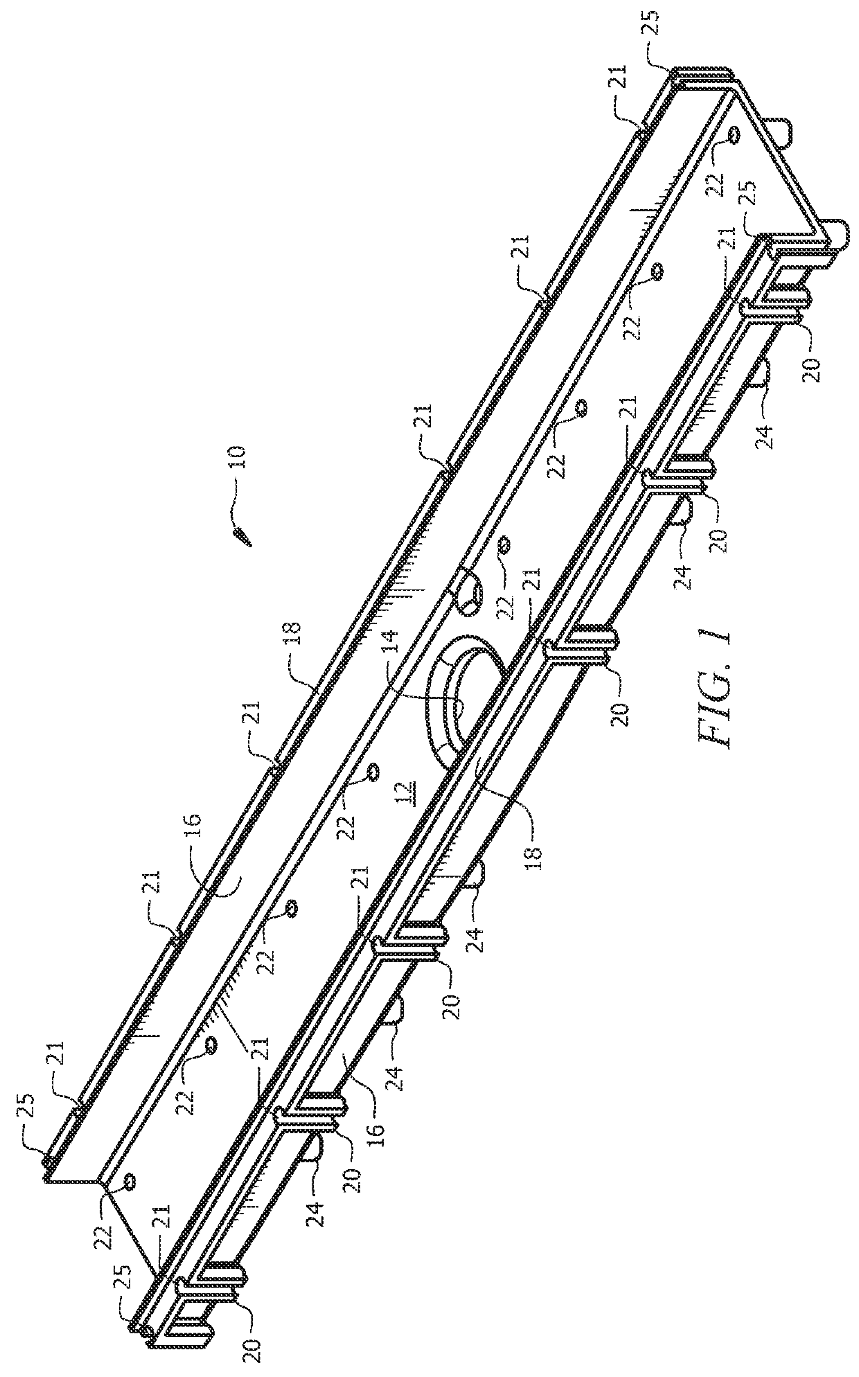
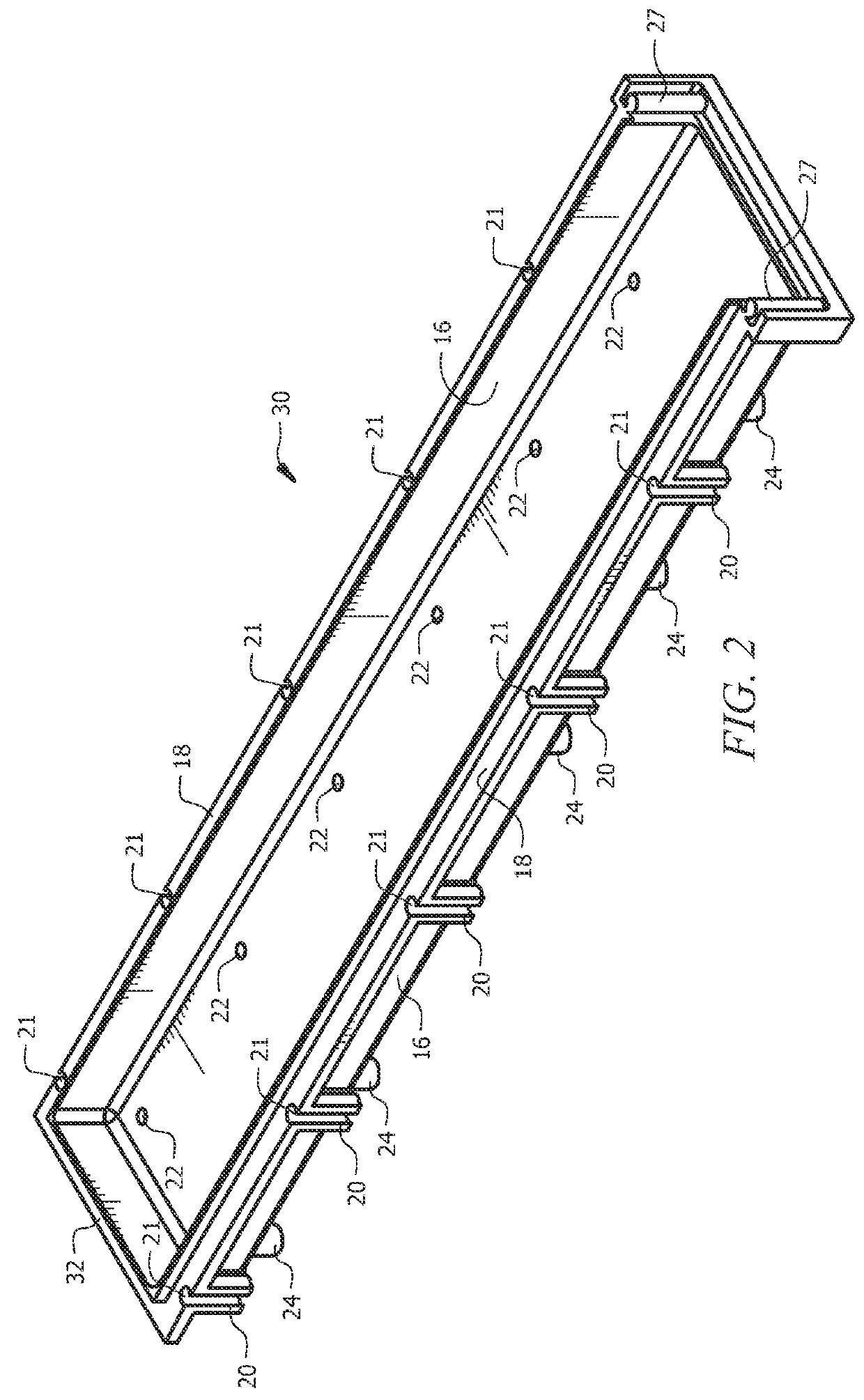
[0038]The novel structure is denoted as a whole in FIG. 1 by the reference numeral 10.

[0039]Elongate linear drain 10 preferably includes rectangular bottom wall 12 having drain aperture 14 formed therein. Drain aperture 14 is centered with respect to the length of linear drain 10 in this embodiment but there is no requirement that it be centered. Bottom wall 12 is sloped in all embodiments so that water is directed into said drain aperture 14. The location of drain aperture 14 is dictated by the environment in which novel structure 10 is used.

[0040]Two longitudinally extending upstanding side walls having a common height, collectively denoted 16, are mounted to the longitudinally extending edges of rectangular bottom wall 12 and collectively define the depth of linear drain 10. Horizontally extending flanges, collectively denoted 18, are connected to said upstanding side walls and extend therefrom in an outboard direction. Each flange 18 is spaced slightly downwardly from the top ed...


PUM


Abstract

An elongate linear drain for a shower includes an elongate, channel-shaped drain body, an elongate, channel-shaped extension that is connectable to either end of the drain body, elongate inserts that are nested within the drain body and the extension, and end walls that cap the ends of the drain body and the ends of the extension. Mounting members are formed along an outboard side of each sidewall of the drain body and the extensions and the mounting members are engaged by float sticks to facilitate the sloping of the floor that leads to the linear drain. Height adjustment screws formed in the respective bottom walls of the drain body and extensions enable height adjustment of the inserts. This enables the tile that overlies the shower floor to be flush with the tile that overlies the insert.

Description

BACKGROUND OF THE INVENTION[0001]1. Field of the Invention[0002]This invention relates to the art of construction. More specifically, it relates to elongate drains for shower installations.[0003]2. Brief Description of the Related Art[0004]The drain of a shower is most often positioned in the center of a shower floor and the floor is sloped in all directions to direct water to the drain.[0005]It is sometimes advantageous, however, to provide an elongate drain that extends the entire width or length of a shower stall. If such a drain is positioned along a center line of the shower, only two downwardly inclined slopes are needed, i.e., one on each side of the drain. If such a drain is positioned on a border of the shower, only one slope leading to the drain is needed. The drain itself has a central opening and the bottom wall of the drain is sloped toward such opening.[0006]U.S. Pat. No. 6,155,015 to the present inventor, entitled Method For Making A Sloped Floor, discloses commercial...

Claims


Application Information

Patent Timeline
IPC IPC(8): A47K3/00E03C1/22A47K3/40
CPCE03C1/22A47K3/40E03F3/046E03F2005/0413E03F5/0408Y02A30/60E03F2005/0414
Inventor KIRBY, MARK E.
Owner GOOF PROOF PROD LLC
Why Eureka
Try Eureka