
Method of forming an implantable device

a technology of scaffolding and implants, which is applied in the field of implantable scaffolding devices, can solve the problems of reducing the growth rate of tissue, affecting the quality of tissue, so as to achieve the effect of greater and beneficial tissue ingrowth

Active Publication Date: 2016-05-31
ETHICON INC
View PDF61 Cites 392 Cited by
  • Summary
  • Abstract
  • Description
  • Claims
  • Application Information

AI Technical Summary

Benefits of technology

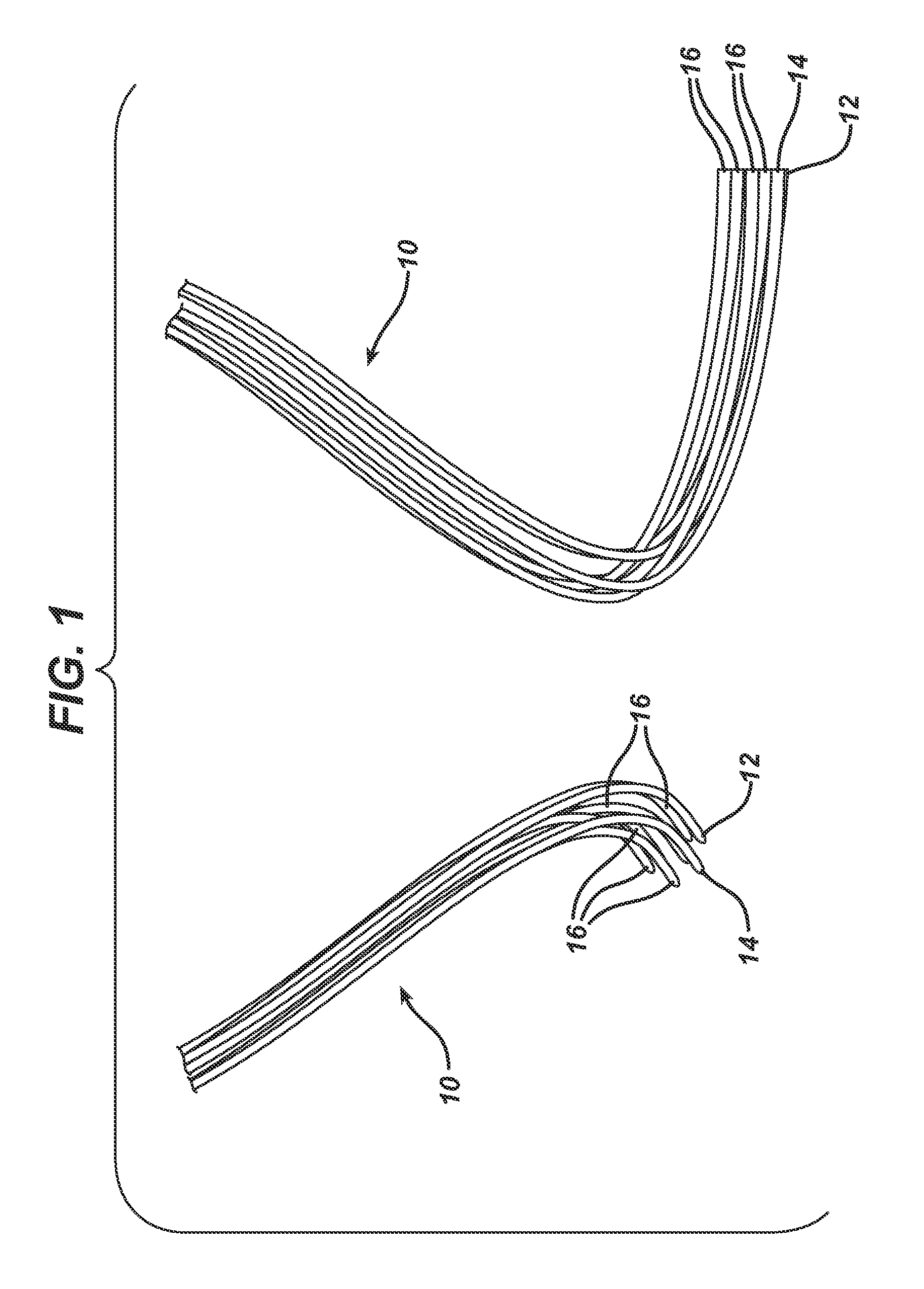
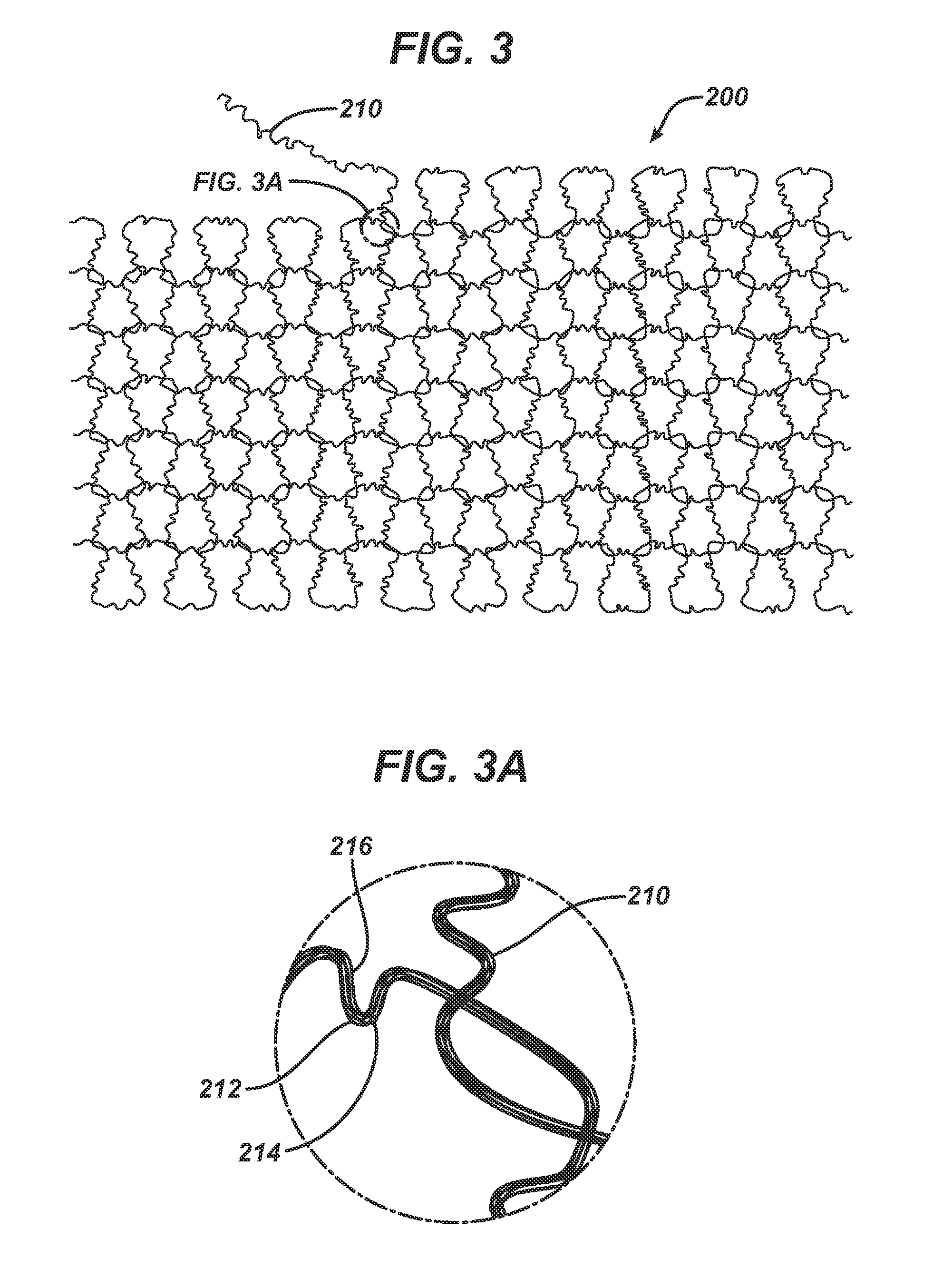
[0005]The present invention is directed to an implantable device for repair or augmentation of tissue, and method of making and using the device. The implantable device of the present invention is a unique three-dimensional arrangement of absorbable and non-absorbable materials to form a flexible three dimensional material having a soft or stiff feel, which can be made into a variety of thicknesses and densities. The design of the implantable device is initially uniform but appears random due to manufacturing processes, which provides a number of benefits and allows for greater and beneficial tissue ingrowth during absorption and once absorption is complete.
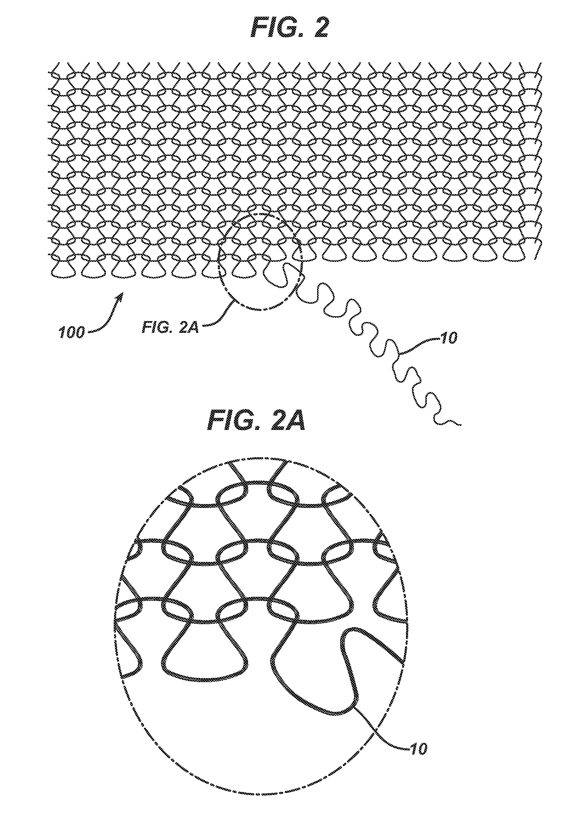
[0006]In one embodiment of the present invention, there is provided a method of forming an implantable device, including the steps of: forming a first yarn and a second yarn, where at least one of the first yarn and second yarns includes a first non-absorbable filament and at least one of the first yarn and second yarns includes a first absorbable filament, the first absorbable filament having a lower melting point than the first non-absorbable filament; forming an initial woven structure including the first yarn and second yarn; subjecting the initial woven structure to a first heat treatment at a first temperature sufficient to cause shrinkage of the first absorbable filament, and thus buckling at least the second yarn and forming an initial heated structure; heating the initial heated structure to a second temperature, the second temperature being higher than the first temperature, where at least a portion of the first absorbable filament is melted; and allowing the heated loose knit weave to cool to form a resulting implantable device.
[0007]In another embodiment, there is provided an implantable device having a random orientation of a non-absorbable filament, formed by the method including the steps of: forming a first yarn and a second yarn, where at least one of the first yarn and second yarns includes a first non-absorbable filament and at least one of the first yarn and second yarns includes a first absorbable filament, the first absorbable filament having a lower melting point than the first non-absorbable filament; forming an initial woven structure including the first yarn and second yarn; subjecting the initial woven structure to a first heat treatment at a first temperature sufficient to cause shrinkage of the first absorbable filament, and thus buckling at least the second yarn and forming an initial heated structure; heating the initial heated structure to a second temperature, the second temperature being higher than the first temperature, where at least a portion of the first absorbable filament is melted; and allowing the heated loose knit weave to cool to form a resulting implantable device.

Problems solved by technology

Typical scaffolds, however, include a high amount of non-absorbable materials, which remain in the body for a significant length of time, and may remain forever.
Given the high level of non-absorbable materials, the scaffold may be felt by the user, or may complicate movement or flexibility.
Some scaffolds are made from entirely bioabsorbable materials, and over time will degrade and be absorbed into the body.
While some degree of non-absorbable materials may be desired, scaffold devices including non-absorbable materials may be felt by the user long after implantation, or may restrict movement or flexibility of the user after implantation.

Method used


Image

  • Method of forming an implantable device
  • Method of forming an implantable device
  • Method of forming an implantable device

Examples


example 1

Testing of Material after Implantation of 7, 14 and 28 Days

[0113]A study was conducted to test pullout force of the inventive material after implantation into rabbits. Samples of the inventive material (including fibers of polypropylene, polyglactin 910 and polydioxanone processed using a heating gap of 2.35 mm) and a control material (Gynemesh®, a non-absorbable polypropylene soft mesh implant) were implanted into rabbits. Two different sized implants were used for each of the inventive material and the control. The “small” implant was a 1.5 cm×1.0 cm sheet covered by a 1.0 cm×1.4 cm polyethylene sheath so that a 0.5 cm×1.0 cm section was uncovered. The “large” implants were sized to be 2.0 cm×1.0 cm, covered by a 1.0 cm×1.4 cm polyethylene sheath so that a 1.0 cm×1.0 cm section was uncovered. The sheath and implantable materials were ultrasonically welded. The sheath blocked or limited tissue ingrowth above the tissue plane and provided a place to grip the construct for testing af...

example 2

Testing of Area Weight, Non-Absorbable Material Amount, and Strength of Materials

[0122]Preparation of Initial Woven Structures

[0123]Three implantable materials were prepared, each with varying amounts of absorbable and non-absorbable materials. All knitting was conducted using Alveolar Tamponade processing parameters except for updated loop sizes for flat knitting determined pre-trial and shown below. For Alveolar Tamponade, two of the same round knitted tubes (socks) were produced first. Both tubes were then un-knitted in parallel and the resulting kinked filament yarn was flat knitted as an initial loose woven structure. The filaments used to make the materials included Vicryl®, which was dyed to show a purple color, PDS and polypropylene. Sock A was made with a first absorbable material and a second absorbable material. Sock B was made with a first absorbable material, a second absorbable material, and a first non-absorbable material. Sock C was made with a first absorbable mater...

example 3

Porosity and Stiffness Testing

[0153]Inventive structures were prepared and tested for porosity and for bending strength, or stiffness. The inventive structure used for this example included vicryl, polypropylene and PDS in a ratio of 5 parts (by weight) vicryl, 1 part polypropylene (by weight) and 1 part PDS (by weight). The initial loose woven structure was prepared, and was subjected to a first heating at 103° C. in a 1.5 mm gap. The initial heated structure was then subjected to a second heating at 105° C. in a 0.9 mm gap, providing the final resulting device. The resulting device was substantially flat and had a board-like shape.

[0154]Stiffness of the device was measured using a three-point bending stiffness test, specifically using a Zwick Roell tensile test. For this testing, a trapeze shaped indenter was pressed onto a test section of the inventive device, measuring about 50 mm×50 mm, where the device was placed over a 12.5 mm gap. The gap allowed the test section to be press...


PUM

PropertyMeasurementUnit
thicknessaaaaaaaaaa
temperatureaaaaaaaaaa

Abstract

An implantable structure, method for making the structure and method for using the structure, where the structure includes a combination of non-absorbable and absorbable components, and the implantable structure has a randomly uniform array of materials. The resulting implantable structure provides improved tissue ingrowth and flexibility after implantation and after absorption of the absorbable materials.

Description

FIELD OF THE INVENTION[0001]The present invention relates to an implantable scaffolding device for repair or augmentation of tissue, the device including a unique three-dimensional arrangement of absorbable and non-absorbable materials. The materials used, the structure of the device, and the method of making the device all provide improved benefits as an implantable device.BACKGROUND OF THE INVENTION[0002]Implantable scaffolds may be used to repair injured or traumatized body tissue, or to aid in the support of body tissue, such as, cartilage, skin, muscle, bone, tendon and ligament. These implantable scaffolds are intended to not only provide support to the repaired tissue, but also to promote and encourage tissue ingrowth so that the repair can be sustained in the body for an extended period of time. Typical scaffolds, however, include a high amount of non-absorbable materials, which remain in the body for a significant length of time, and may remain forever. Given the high level...

Claims


Application Information

Patent Timeline
Patent Type & Authority Patents(United States)
IPC IPC(8): D01F6/06D04B1/16A61L27/56A61L27/58A61L27/40D03D1/00A61L27/48A61L27/50A61L27/18A61L27/16D01F6/62D02G3/04A61F2/04
CPCA61L27/40A61L27/16A61L27/18A61L27/48A61L27/50A61L27/56A61L27/58D01F6/625D02G3/045D04B1/16C08L23/12C08L67/04D10B2509/08
Inventor LANDGREBE, SUSANNESMITH, DANIELDICK, OLIVER
Owner ETHICON INC
Learn More