Eureka AIR delivers breakthrough ideas for toughest innovation challenges, trusted by R&D personnel around the world.

Ejector for a mobile ground preparation machine

a technology of ejector and mobile ground, which is applied in the direction of cutting machines, roads, roads, etc., can solve the problems of insufficient strength properties as a replacement part, restricting the operability of the ejector plate, and inability to meet the needs of the customer, etc., to achieve satisfactory fit increase the stability of the ejector plate, and improve the effect of stability

Active Publication Date: 2016-05-31
BOMAG
View PDF8 Cites 4 Cited by
  • Summary
  • Abstract
  • Description
  • Claims
  • Application Information

AI Technical Summary

Benefits of technology

[0006]It is an object of the present invention to provide an ejector unit of the above type in which the ejector plate can be removably attached to the milling drum in a particularly stable and secure manner.

Problems solved by technology

The problem frequently encountered in the use of these light-weight ejector plates is that they become deformed and wear out under stress conditions, which restricts their operability.
One particular problem in this respect relates to the region in which the ejector plates are attached to the basic unit and in which the material is weakened, for example, by holes provided for a bolted connection.
However, any deformation of the material is in this region particularly undesirable, since a deformed ejector is difficult to remove from the basic unit for the purpose of replacement.
A further problem relates to the widespread use of ejector plates not made by the original manufacturer, which have insufficient strength properties as a replacement part.

Method used


Image

  • Ejector for a mobile ground preparation machine
  • Ejector for a mobile ground preparation machine
  • Ejector for a mobile ground preparation machine

Examples


Embodiment Construction

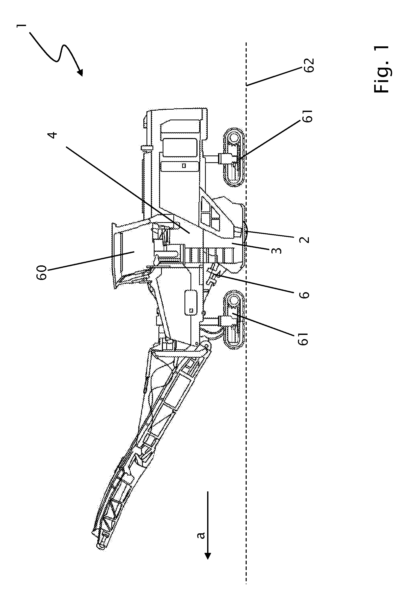
[0034]FIG. 1 shows a ground milling machine 1 of the front loading type comprising a centrally disposed milling drum 2 located in a drum housing 3. The working direction (forward direction) is denoted by the arrow ‘a’. The ground milling machine 1 further comprises a machine frame 4 comprising a control platform 60 and crawler tracks 61 mounted on the machine frame 4 by means of lifting columns so as to be vertically adjustable (it being also possible to use wheeled undercarriages here as an alternative).

[0035]In the operating mode, the ground milling machine 1 travels on the ground 62 in the machine direction ‘a’ and, in doing so, mills off ground material from the ground 62 by means of the milling drum 2 having been set in rotation. As a result of the rotation of the milling drum 2, the milled material is flung from the drum housing 3 onto a conveyor belt 6, which communicates with the drum housing 3, for removal of said material.

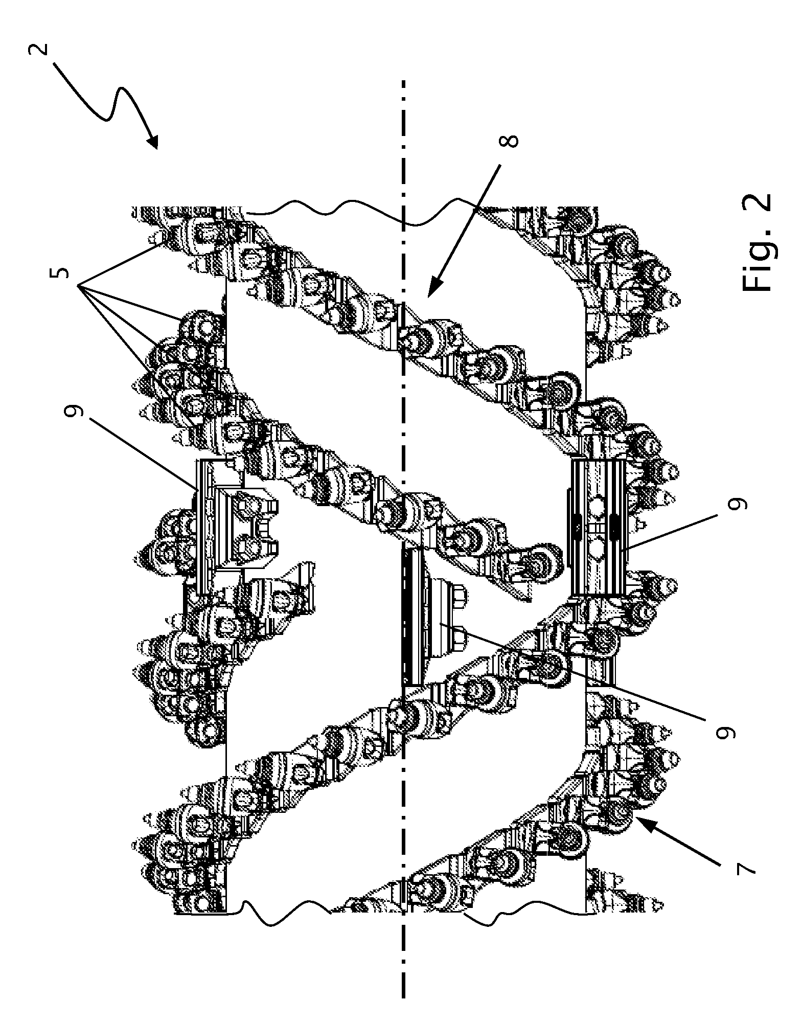
[0036]As shown in FIG. 2, a plurality of cutting to...


PUM


Abstract

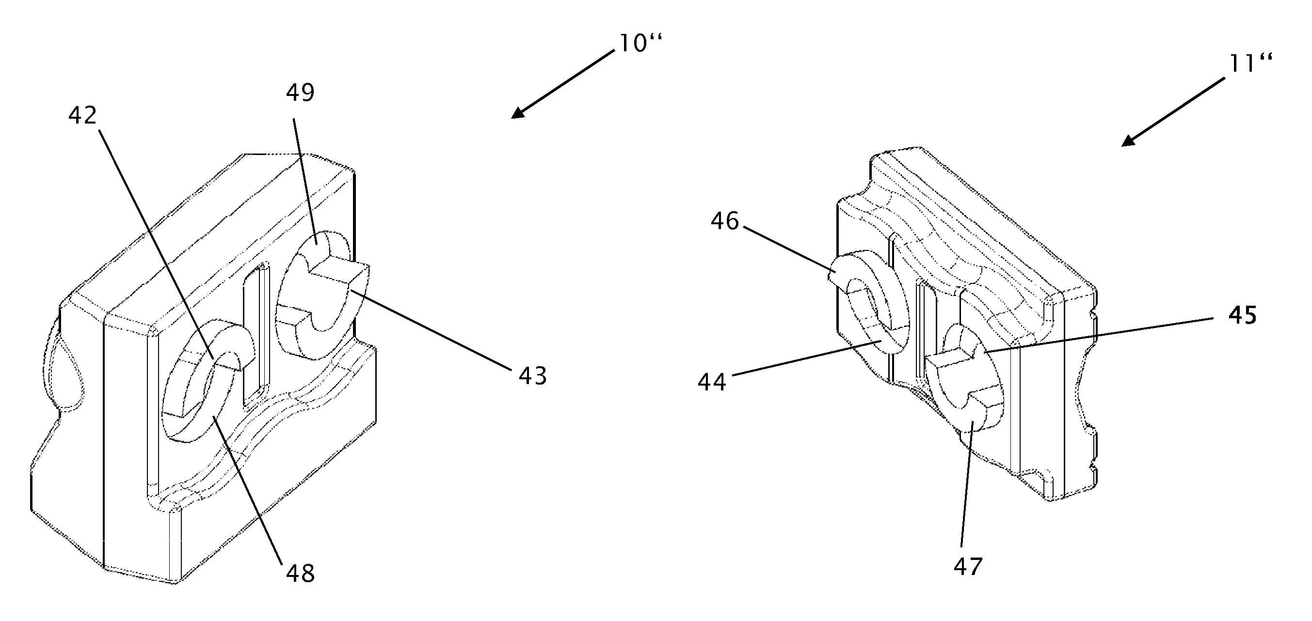
Described is an ejector unit for a milling drum of a mobile ground preparation machine comprising a discharge side and a reverse side that is opposite to the discharge side. It comprises a basic unit on the drum and an ejector plate, which is held on the basic unit by means of screw-threaded bolts. There is a positive fit between the basic unit and the ejector plate, which positive fit involves at least one pin, on the one hand, and at least one complementary cylindrical counterbore on the other hand, whereby the at least one pin and the at least one ejector are oriented so as to be coaxial to the longitudinal axis of the screw-threaded bolts. Preferably, a shoulder is also provided along the base of the basic unit on its side facing the ejector plate, and the ejector plate has at least one complementary shoulder, whereby the shoulder on the basic unit and the at least one shoulder on the plate have meshing regions, which in the mounted state prevent transverse displacements in three directions.

Description

CROSS-REFERENCE TO RELATED APPLICATIONS[0001]The present application claims priority under 35 U.S.C. §119 of German Patent Application No. 10 2012 012 615.8, filed Jun. 19, 2012, the disclosure of which is hereby incorporated herein by reference in its entirety.FIELD OF THE INVENTION[0002]The present invention relates to an ejector unit for a milling drum of a mobile ground preparation machine, which ejector unit comprises a basic unit on the drum side and a replaceable ejector plate having a discharge side and a reverse side located opposite to the discharge side and that is removably attached to the basic unit by means of bolts.BACKGROUND OF THE INVENTION[0003]Mobile ground preparation machines of this type are cold milling machines, stabilizers, surface miners, and recyclers, in particular, which are used in the construction of paved traffic areas and are included below in the term “ground milling machines”. The working implements consist of a milling drum that is provided with a...

Claims


Application Information

Patent Timeline
Patent Type & Authority Patents(United States)
IPC IPC(8): E21C35/18E01C23/088
CPCE01C23/088
Inventor WACHSMANN, STEFFEN
Owner BOMAG
Why Eureka
Eureka Blog
Learn More