
Matte box assembly

a box and assembly technology, applied in the field of matte box assembly, can solve the problems of large hinges, distortion of images being captured, and cumbersome design of hinges, and achieve the effects of low cost, simple construction, and less distortion

Inactive Publication Date: 2012-02-07
WOOD DENNIS
View PDF3 Cites 3 Cited by
  • Summary
  • Abstract
  • Description
  • Claims
  • Application Information

AI Technical Summary

Benefits of technology

"The invention is a matte box assembly for use with a camera rig that includes a matte frame and a hood. The matte frame is supported on a pair of parallel mounting rails and a rail mount is fixed on the camera rig. A support frame is provided with two side frame members and an upper and lower frame member that can be adjusted relative to each other. The hinge coupling the matte frame to the support frame allows for pivotal movement between an in-use position and an out-of-use position. The assembly provides a secure and stable way to use a matte box with a camera rig."

Problems solved by technology

Accordingly the matte frame is not supported in a stable manner and minor relative movements of the filters supported by the matte frame relative to the lens may cause distortions in the image being captured.
Due to the support frame and hinges only supporting the matte frame on one side of the lens, the hinges are designed to be rather large and cumbersome as they are required to have sufficient clamping force to support the matte frame from only one side thereof.

Method used


Image

  • Matte box assembly
  • Matte box assembly
  • Matte box assembly

Examples


Embodiment Construction

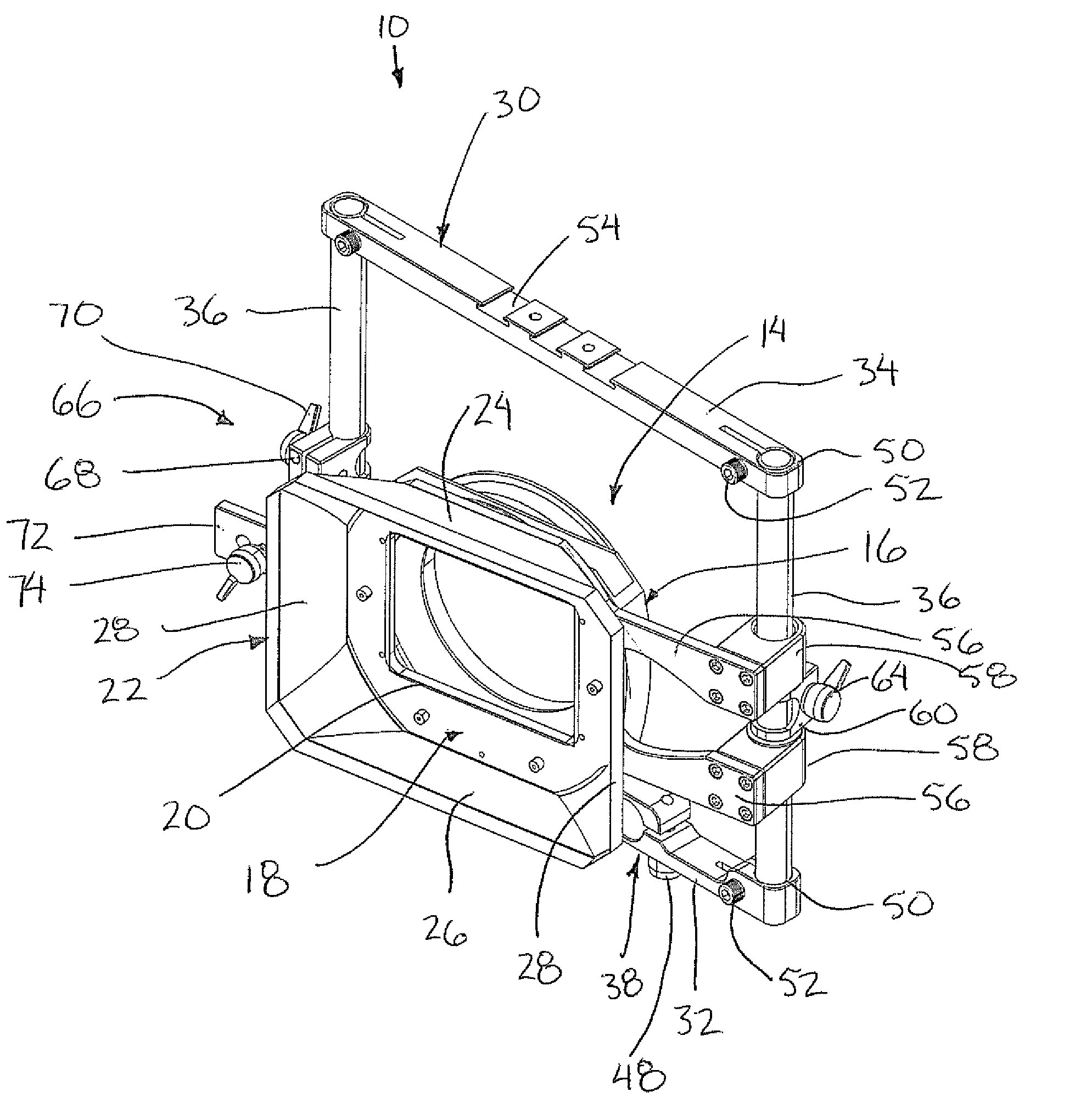
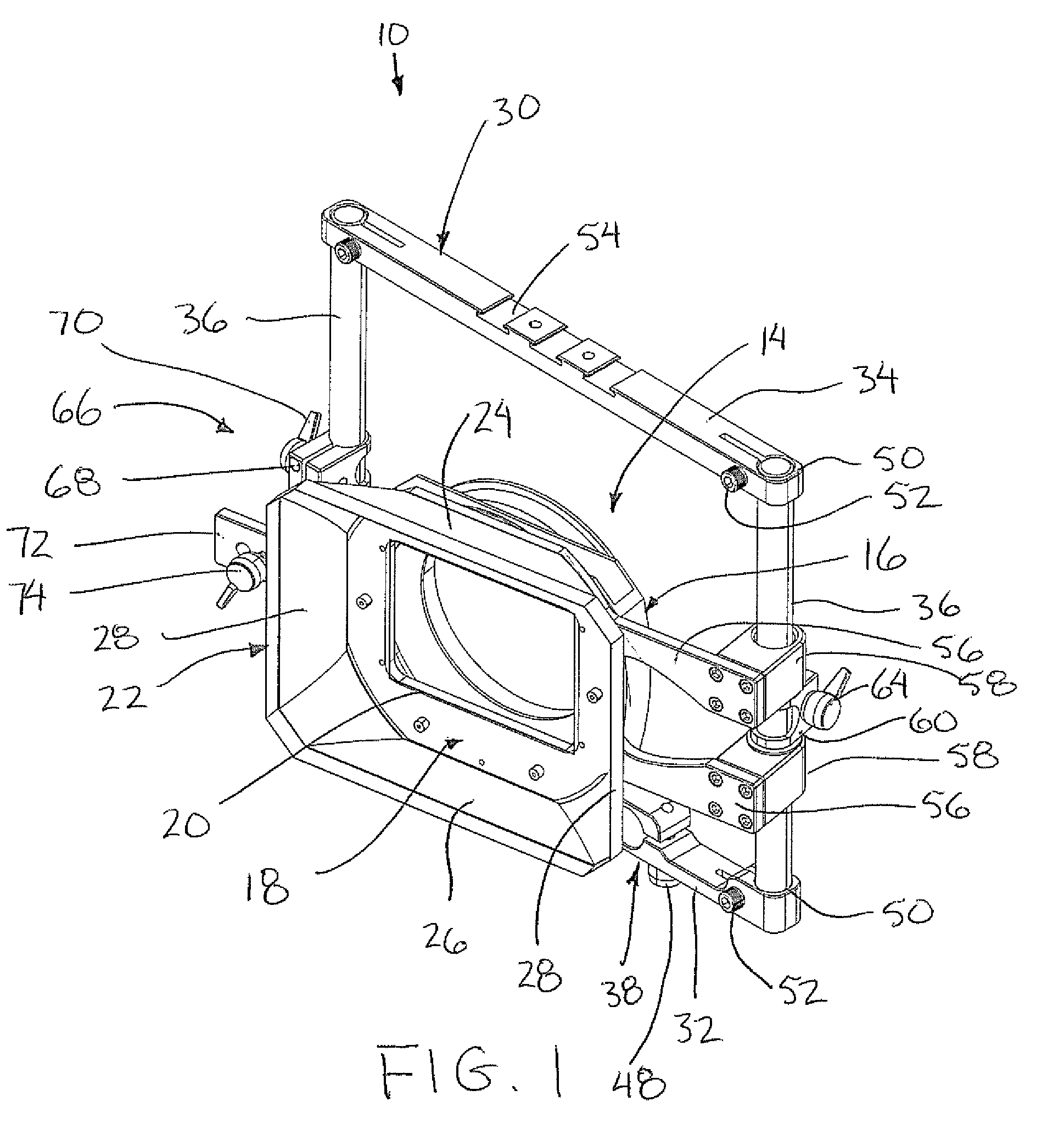
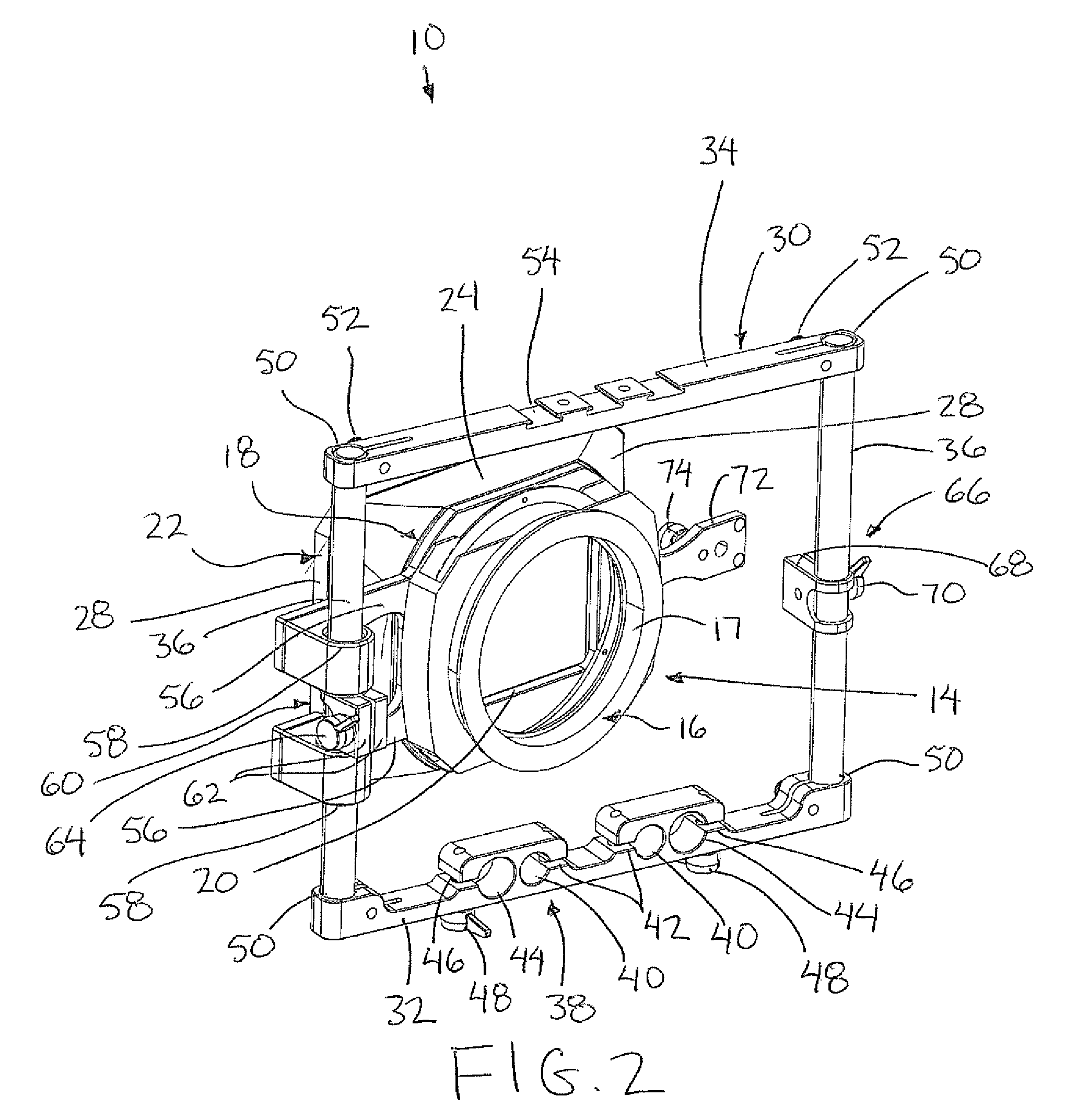
[0038]Referring to the accompanying figures there is illustrated a matte box assembly generally indicated by reference numeral 10. The assembly 10 is typically used with a camera rig comprising a camera body having a lens which is directed in a forward longitudinal direction to capture images. A pair of mounting rails 12 are supported parallel and spaced apart from one another to extend in the longitudinal direction of the camera along the full length of the camera rig. Various camera accessories including the matte box assembly 10 are supported on the mounting rails 12 so as to be in fixed relation to the camera body.

[0039]The matte box assembly generally comprises a matte frame 14 having an inner side 16 for mounting in close proximity about the lens of the camera and an outer side 18 positioned forwardly of the inner side upon which filters can be supported. The inner side 16 typically comprises a generally cylindrical collar 17 arranged to receive the lens of the camera therein....


PUM


Abstract

A matte box assembly is arranged for use with a camera rig including a camera body supported on a pair of parallel and spaced apart mounting rails extending in a longitudinal direction. The matte box assembly includes a matte frame surrounding a lens opening for alignment with the camera lens and a filter mount to support a lens filter spanning the lens opening. A support frame is arranged to be mounted on the mounting rails of the camera rig onto which the matter frame is supported for pivotal movement about a vertical axis between an in-use position aligned with the camera lens and an out-of-use position offset to one side of the camera lens.

Description

[0001]This application claims the benefit under 35 U.S.C.119(e) of U.S. provisional application Ser. No. 61 / 170,694, filed Apr. 20, 2009.FIELD OF THE INVENTION[0002]The present invention relates to a matte box assembly for use with a camera comprising a camera body supported on a pair of parallel and spaced apart mounting rails such that a matte frame of the matte box assembly is supported for pivotal movement relative to the mounting rails.BACKGROUND[0003]The use of matte boxes are known for reducing unwanted lens flare caused by lights or the sun, or for holding suitable glass or plastic filters in front of the lens. A common type of camera rig with which a matte box is used comprises two mounting rods which are supported parallel and spaced apart from one another to extend in a longitudinal direction. A camera body is anchored onto the rods at a first position thereon to be directed forwardly in the longitudinal direction for capturing images. Forwardly of the camera body along t...

Claims


Application Information

Patent Timeline
Patent Type & Authority Patents(United States)
IPC IPC(8): G03B11/04
CPCG03B11/00
Inventor WOOD, DENNIS
Owner WOOD DENNIS
Learn More