AI technical title is built by Patsnap AI team. It summarizes the technical point description of the patent document.
a voltage converter and linearization control technology, applied in the direction of dc-dc conversion, power conversion systems, instruments, etc., can solve the problems of unstable operating point of boost and buck-boost converters, nonlinear operation of control loops, and difficult control of the system under these nonlinear effects
Active Publication Date: 2016-06-14
CIRASYS +1
View PDF43 Cites 0 Cited by
Summary
Abstract
Description
Claims
Application Information
AI Technical Summary
This helps you quickly interpret patents by identifying the three key elements:
Problems solved by technology
Method used
Benefits of technology
Problems solved by technology
Switching from one state to another during operation and the accompanying nonlinearity of power converters creates problems.
But, control of the system under these nonlinear effects becomes difficult when certain performance objectives must be met.
However, use of this method requires making several assumptions, one of them being so-called “small signal operation.” This works well for asymptotic stability in the neighborhood of the operating point, but ignores large signal effects which can result in nonlinear operation of the control loop when, for example, an amplifier saturates during startup, or during transient modes, such as load or input voltage changes.
Unstable zero dynamics associated with TEM with switch on-time sampling in the continuous conduction mode (“CCM”) prevent the use of an input-output feedback linearization because it would result in an unstable operating point for boost and buck-boost converters.
This makes control design extremely difficult.
Method used
Image
Click on the blue label to locate the original text in one second.
Reading with bidirectional positioning of images and text.
Examples
Embodiment Construction
[0022]While the making and using of various embodiments of the present disclosure are discussed in detail below, it should be appreciated that the present disclosure provides many applicable inventive concepts that can be embodied in a wide variety of specific contexts. The specific embodiments discussed herein are merely illustrative of specific ways to make and use the invention and do not delimit the scope of the invention.
[0023]The present disclosure provides a method and apparatus for controlling a voltage converter circuit to realize a power converter or a power inverter. A power converter usually refers to a device that delivers a regulated output voltage in response to an unregulated input voltage. A power inverter in power electronics usually refers to a power converter device that delivers an ac output voltage in response to a dc input voltage although an arbitrary time-varying output waveform for one of either a dc voltage input or an ac voltage input is possible. In part...
PUM
Abstract
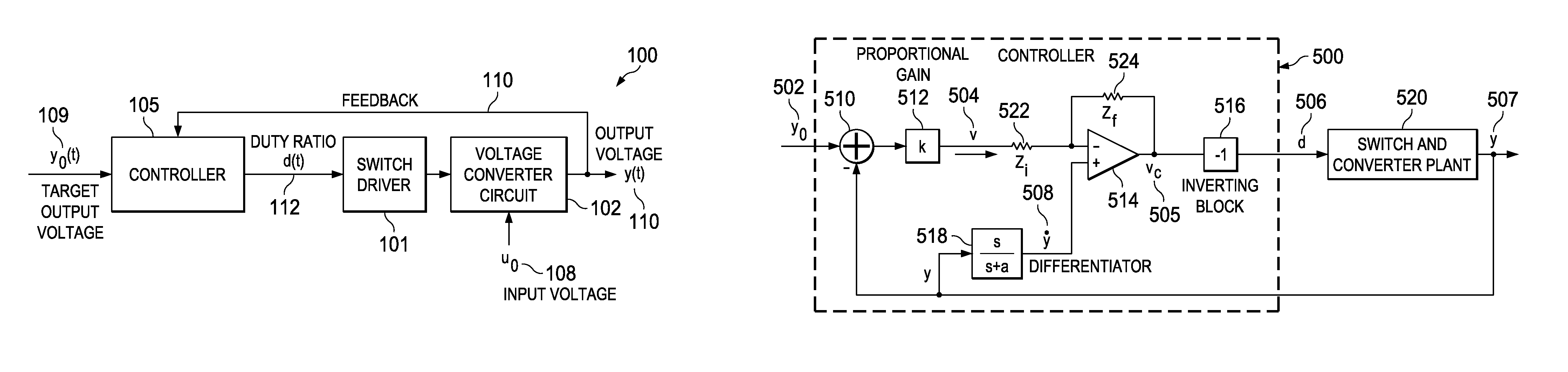
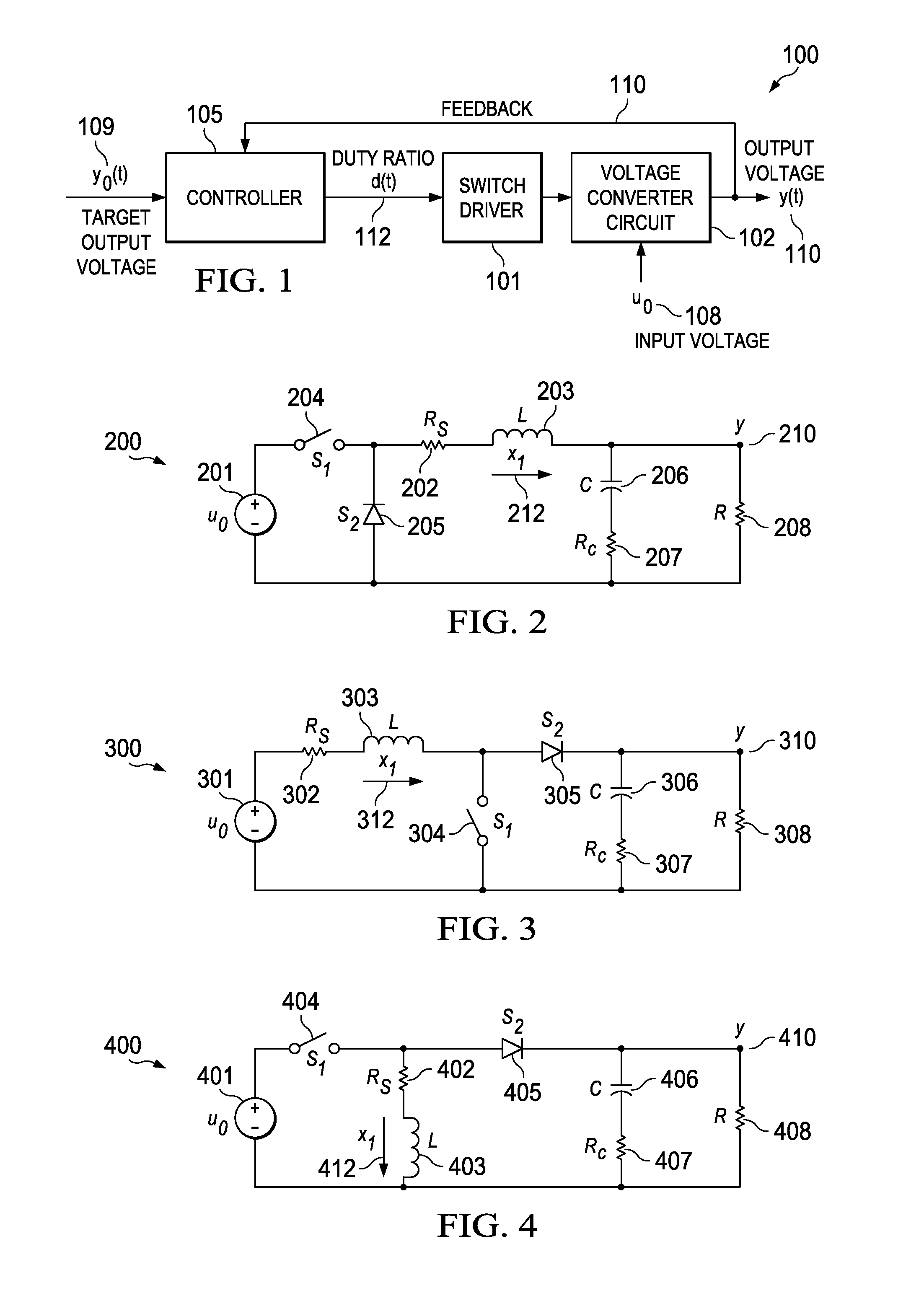
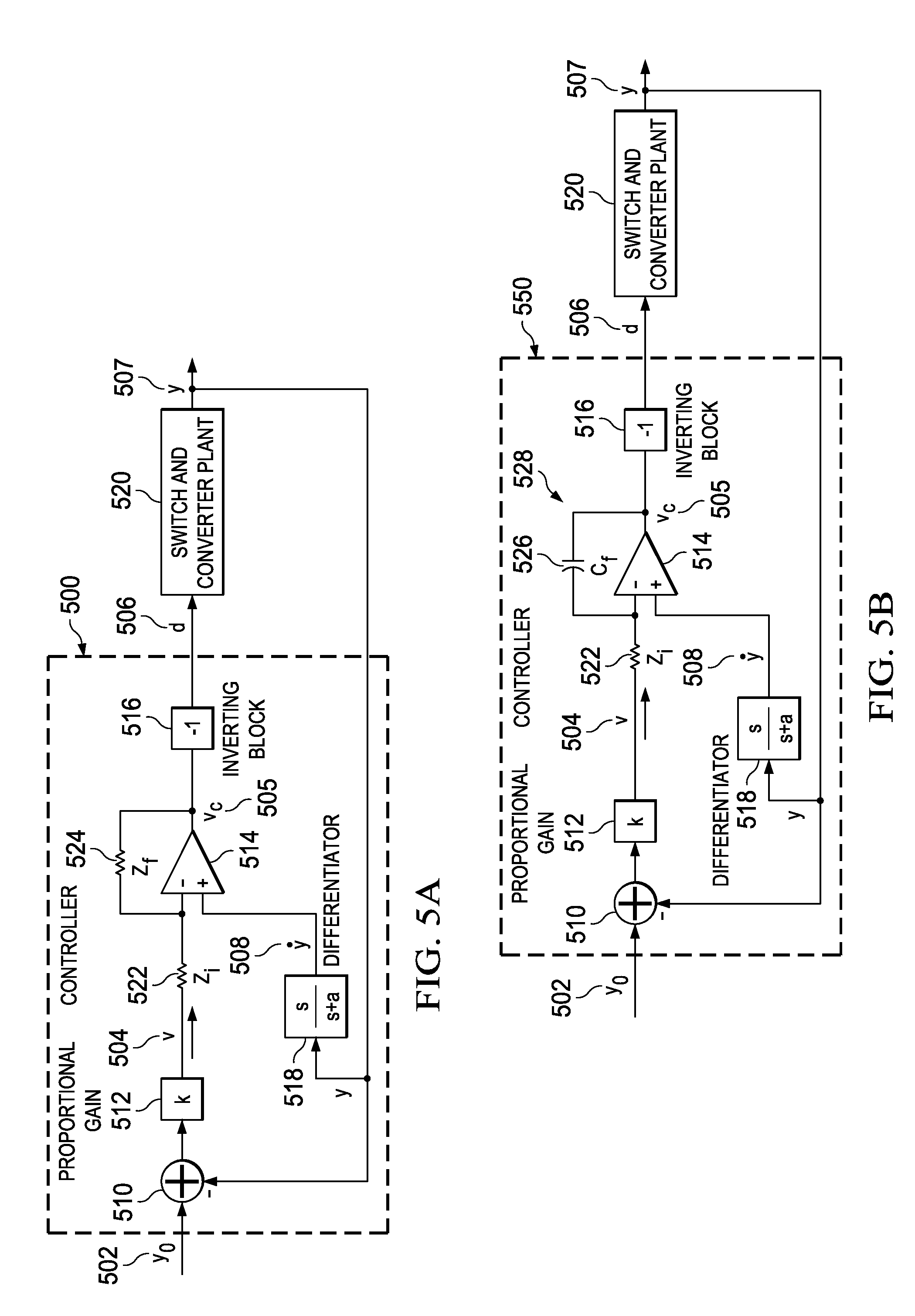
A voltage converter for converting an input voltage to an output voltage is disclosed. The voltage converter includes a voltage converter circuit having a set of switches, a switch driver connected to the voltage converter circuit, a controller connected to the switch driver and the output voltage, a target output voltage connected to the controller, a control signal generated by the controller for the switch driver that includes a duty ratio based on the target output voltage and the output voltage. The switch driver is configured to apply the control signal to the set of switches and the voltage converter circuit generates the output voltage based on the duty ratio to match the target output voltage.
Description
CROSS REFERENCE TO RELATED APPLICATIONS[0001]This application claims priority to U.S. Provisional Application No. 61 / 869,387 filed Aug. 23, 2013. This application is a continuation in part of U.S. application Ser. No. 13 / 938,333 filed Jul. 10, 2013, which claims priority to U.S. Provisional Application No. 61 / 670,520 filed Jul. 11, 2012 and is a continuation in part of U.S. application Ser. No. 13 / 373,673 filed Nov. 22, 2011, now U.S. Pat. No. 8,803,498, which claims priority to U.S. Provisional Application No. 61 / 458,850 filed Dec. 2, 2010 and is a continuation in part of U.S. application Ser. No. 12 / 487,242 filed Jun. 18, 2009, now U.S. Pat. No. 8,810,221. This application is a continuation in part of U.S. application Ser. No. 13 / 720,850 filed Dec. 19, 2012, which claims priority to U.S. Provisional Application No. 61 / 578,137 filed Dec. 20, 2011. Each of the patent applications identified above is incorporated herein by reference in its entirety to provide continuity of disclosure...
Claims
Application Information
Patent Timeline
Application Date:The date an application was filed.
Publication Date:The date a patent or application was officially published.
First Publication Date:The earliest publication date of a patent with the same application number.
Issue Date:Publication date of the patent grant document.
PCT Entry Date:The Entry date of PCT National Phase.
Estimated Expiry Date:The statutory expiry date of a patent right according to the Patent Law, and it is the longest term of protection that the patent right can achieve without the termination of the patent right due to other reasons(Term extension factor has been taken into account ).
Invalid Date:Actual expiry date is based on effective date or publication date of legal transaction data of invalid patent.
Patent Type & AuthorityPatents(United States)
IPC IPC(8): H02M3/156H02M3/158H03K7/08
CPCH02M3/156H02M3/158H03K7/08
InventorPADUVALLI, VIKAS V.HUNT, LOUIS R.BALSARA, PORAS T.TAYLOR, ROBERT J.

