Pulse generator having an efficient fractional voltage converter and method of use

a fractional voltage converter and pulse generator technology, applied in the field of power supply circuitry, can solve the problems of undesirable complex and inefficient power supply circuits, complex and inefficient switching regulator circuitry, and low efficiency of circuitry providing the foregoing, so as to reduce the number of components, and save energy

Inactive Publication Date: 2006-08-03
ADVANCED NEUROMODULATION SYST INC
View PDF5 Cites 92 Cited by
  • Summary
  • Abstract
  • Description
  • Claims
  • Application Information

AI Technical Summary

Benefits of technology

[0015] In order to minimize the number of components used in a voltage converter of a representative embodiment, a capacitive voltage converter circuit uses one or more storage capacitors in place of pump capacitors in a voltage generation cycle. In past capacitive voltage multiplier circuits, pump capacitors have been used to generate a voltage from the power supply and storage capacitors have been used in storing the generated voltage until output, and the use of these capacitors as pump or storage capacitors has been mutually exclusive. However, representative embodiments use some of the storage capacitors in place of pump capacitors in order to reduce the number of components used in providing a conversion circuit. Moreover, representative embodiments utilize pump and storage capacitors which are not matched (e.g., not of the same capacitance) when generating voltages. According to a representative embodiment, storage capacitors are relatively large whereas pump capacitors are relatively small, although a combination of storage and pump capacitors is used in generating a particular voltage multiple or fraction of a voltage.
[0016] Representative embodiments do not operate to generate an output voltage until the time that voltage that is needed. For example, by stacking the supply capacitors (e.g., pump capacitors and / or storage capacitors) to form the desired output voltage as that voltage is being requested, representative embodiments avoid a need to discharge a particular source capacitor in order to change the output voltage. Instead, representative embodiments operate to stack the supply capacitors as needed to provide a desired output voltage. Accordingly, there is no energy wasted in the formation of the desired voltage according to some embodiments.

Problems solved by technology

Circuitry providing the foregoing may be relatively complex, perhaps including a number of active components, and often suffers from inefficiencies, e.g., an appreciable amount of the power supply energy is consumed in altering the power supplied from the power source.
However, complex and inefficient power supply circuits are undesirable in a number of situations, such as in certain portable devices using a battery as a power supply.
Accordingly, the use of an inductive voltage multiplier with a battery power supply generally involves the use of complicated and inefficient switching regulator circuitry to convert the direct current from the battery to alternating current for voltage up-conversion.
Electromagnetic noise is often introduced by inductor-based switching regulator circuitry, such as may interfere with data communications, thereby requiring additional shielding and / or circuitry to prevent such electromagnetic noise from interfering with operation of the device.
Accordingly, inductive voltage up-converters are generally undesirable for use in small battery powered devices, such as implantable neurostimulators.
However, such integer multiples of the battery voltage often are not the most efficient voltages.
Further compounding the inefficiencies associated with capacitive voltage multipliers of the prior art is their operation in creating and storing a voltage multiple.
The discharge of the previously stored multiply voltage is a waste of energy which, if done often, can amount to an appreciable drain on the power supply.
For example, where two sequential stimulation pulses of a neurostimulator require different voltages, prior art capacitive voltage multipliers would require discharging of capacitors charged for providing the first voltage for recharging of the capacitors for providing the second voltage, thereby wasting energy.

Method used


Image

  • Pulse generator having an efficient fractional voltage converter and method of use
  • Pulse generator having an efficient fractional voltage converter and method of use
  • Pulse generator having an efficient fractional voltage converter and method of use

Examples


Embodiment Construction

[0025] In order to aid the reader in understanding the concepts of some embodiments, a representative embodiment is described herein with reference to a neurostimulation system. Such a system generally has several design constraints associated therewith, such as limited battery power, small size, high reliability, and efficient operation, particularly relevant to advantages available from voltage converters implementing concepts. However, it should be appreciated that voltage converters provided according to some embodiments may be used in any number host systems or situations. Exemplary embodiments are described herein with reference to providing voltage multiplication. However, one of ordinary skill in the art will readily appreciate that concepts disclosed in relation to voltage multipliers are applicable to voltage dividers as well.

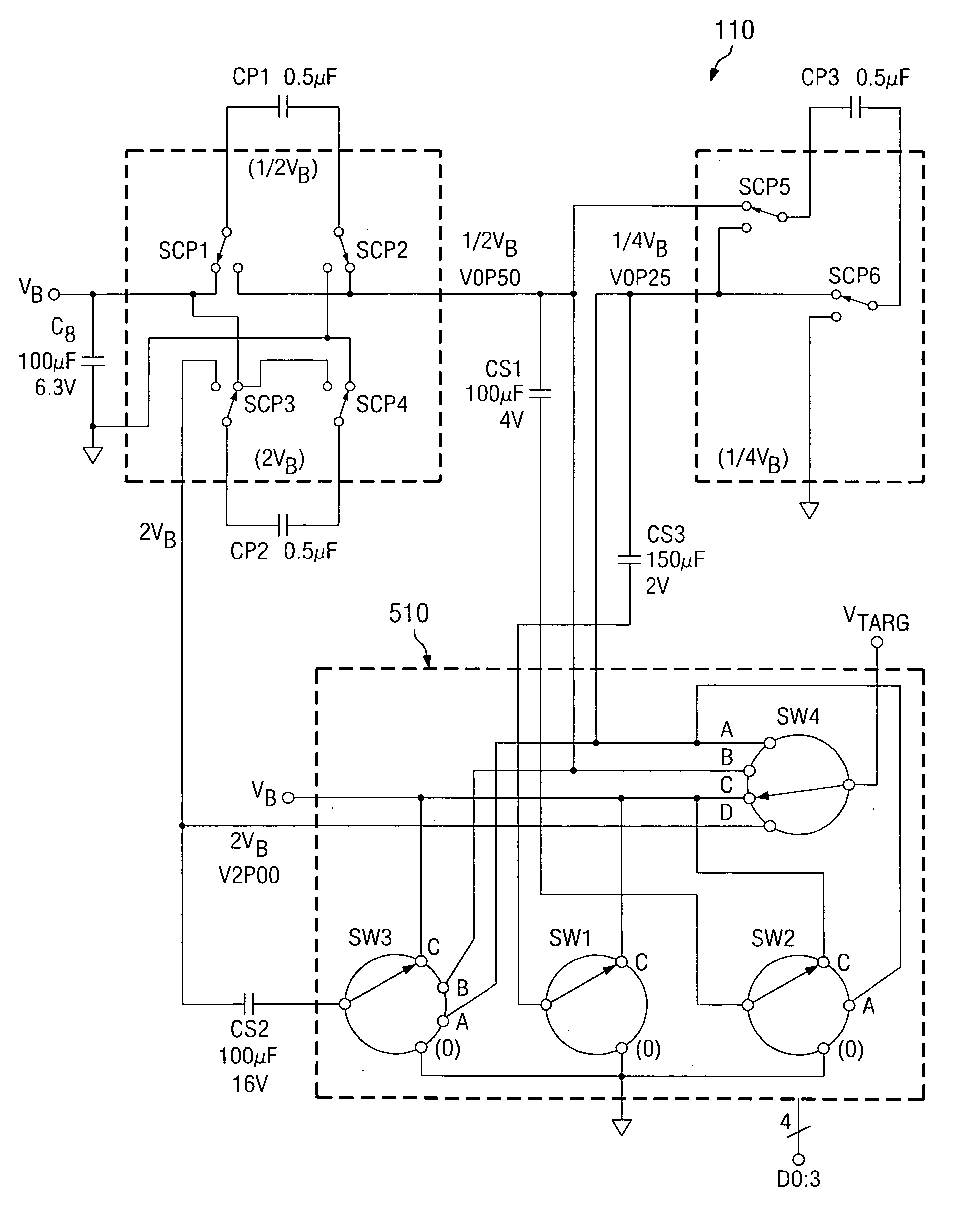
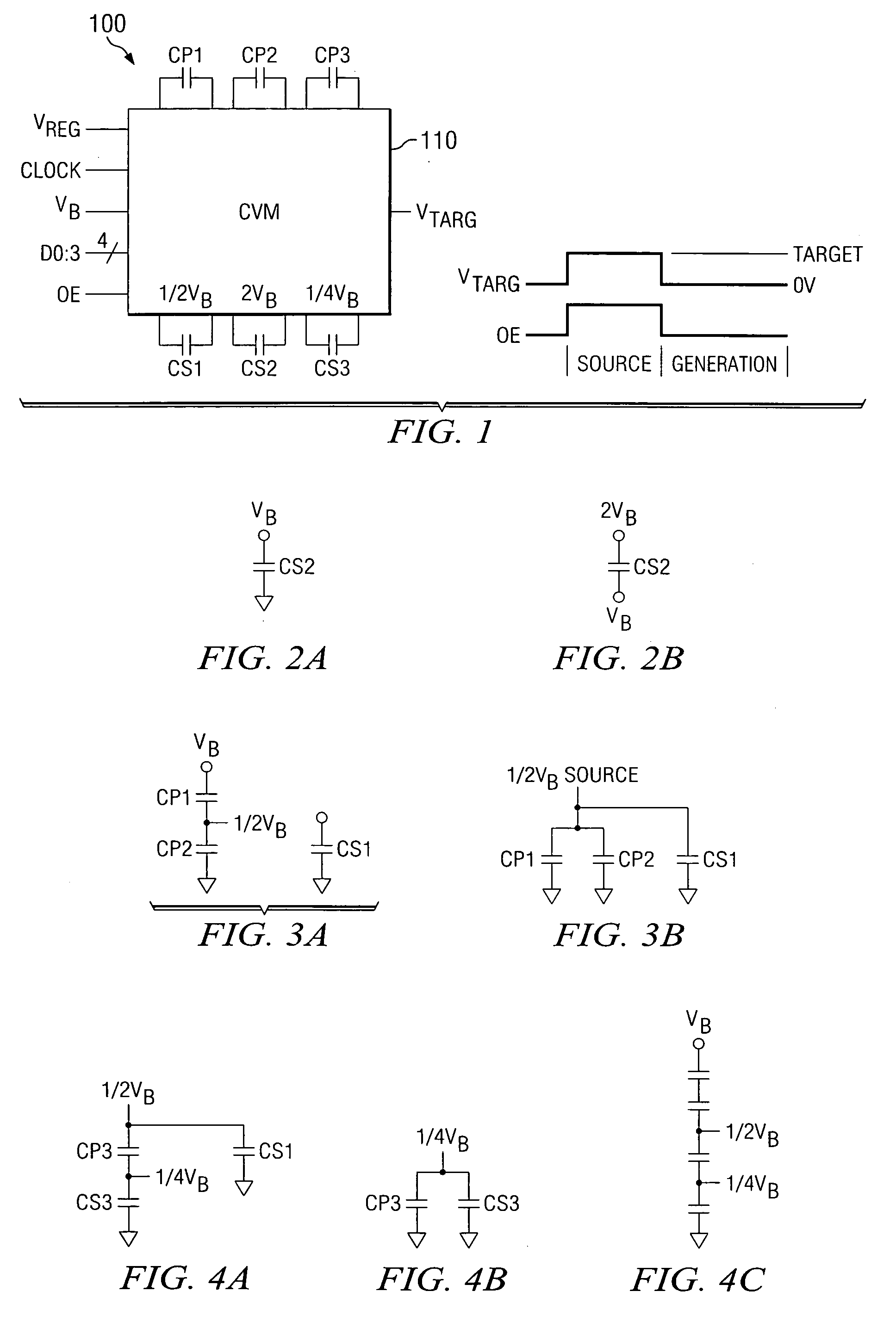
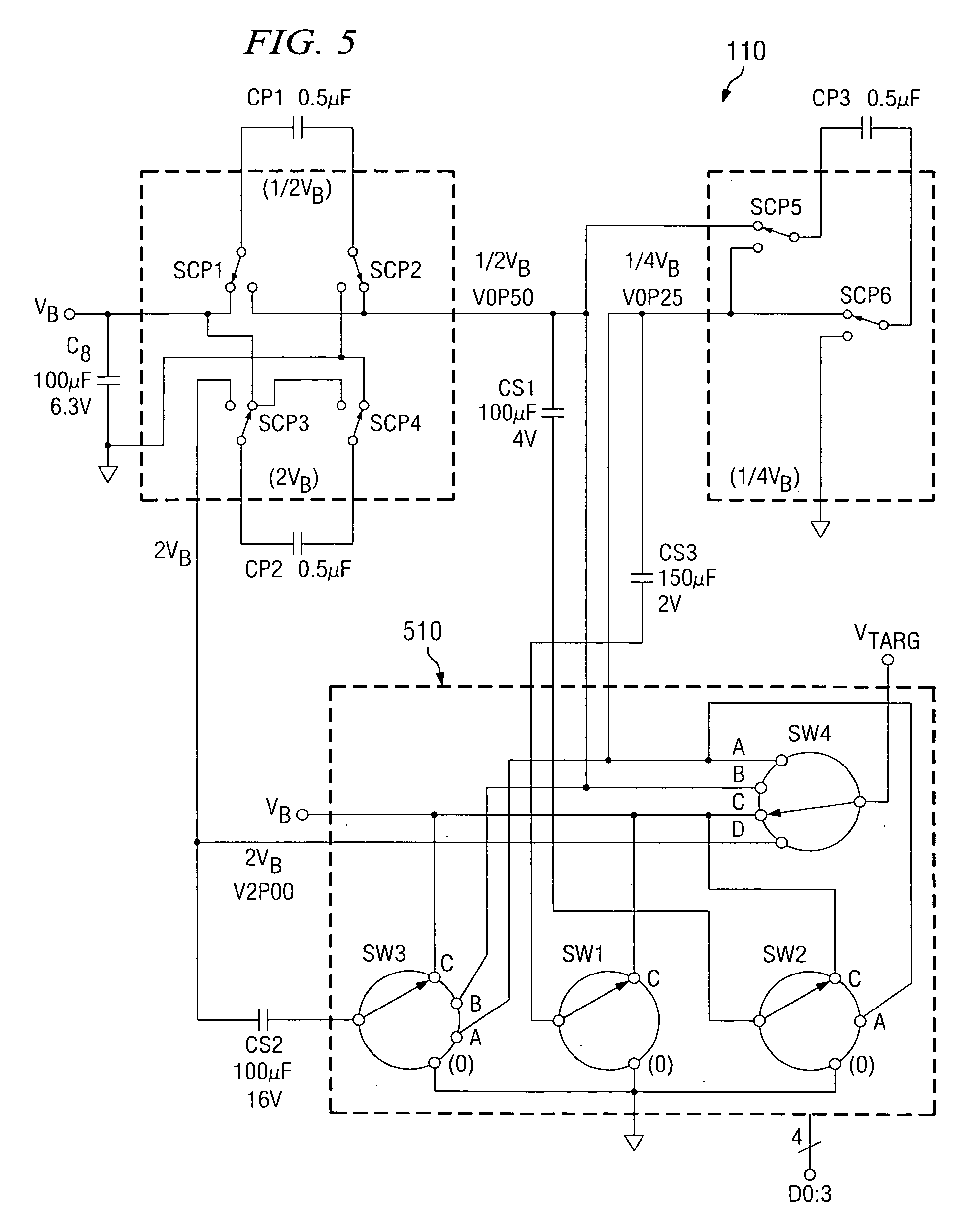
[0026] Directing attention to FIG. 1, a high level block diagram of a voltage multiplier configuration of a representative embodiment is shown as vo...


PUM


Abstract

Disclosed are systems and methods which provide voltage conversion in increments less than integer multiples of a power supply (e.g., battery) voltage. A representative embodiment provides power supply voltage multipliers in a binary ladder distribution to provide a desired number of output voltage steps using a relatively uncomplicated circuit design. By using different sources in various combinations and/or by “stacking” different sources in various ways, the voltage multiplier circuit may be used to provide desired voltages. In order to minimize the number of components used in a voltage converter of an embodiment, a capacitive voltage converter circuit uses one or more storage capacitors in place of pump capacitors in a voltage generation cycle. Also, certain embodiments do not operate to generate an output voltage until the time that voltage is needed.

Description

CROSS-REFERENCE TO RELATED APPLICATIONS [0001] Priority is hereby claimed to U.S. provisional patent application Ser. No. 60 / 648,556 entitled “Efficient Fractional Voltage Converter,” filed Jan. 31, 2005, the disclosure of which is hereby incorporated herein by reference. The present application is related to co-pending and commonly assigned U.S. patent application Ser. No. 11 / 105,191 entitled “Systems and Methods for Precharging Circuitry for Pulse Generation,” filed Apr. 12, 2005, Ser. No. 11 / 122,540 entitled “Multi-Programmable Trial Stimulator,” filed May 5, 2005, and Ser. No. 11 / 105,332 entitled “Fractional Voltage Converter,” filed Apr. 12, 2005, the disclosures of which are hereby incorporated herein by reference.TECHNICAL FIELD [0002] This application relates generally to power supply circuitry and, more particularly, to an efficient voltage multiplier. BACKGROUND OF THE INVENTION [0003] A variety of devices employ power supply circuitry in order to provide voltages and / or c...

Claims


Application Information

Patent Timeline
Patent Type & Authority Applications(United States)
IPC IPC(8): G05F1/10
CPCA61N1/025H02M3/07
Inventor TRANCHINA, BENJAMIN A.ERICKSON, JOHN H.VARRICHIO, ANTHONY J.
Owner ADVANCED NEUROMODULATION SYST INC
Why Eureka
Try Eureka