Antenna mounting structure

A mounting structure and antenna technology, applied in the direction of antenna support/mounting device, etc., can solve the problem of enlargement, etc., and achieve the effect of easy assembly, minimum size of the casing, and minimum number of components

Inactive Publication Date: 2008-09-24
LEJIN ELECTRONICS KUNSHAN COMPUTER CO LTD
View PDF0 Cites 0 Cited by
  • Summary
  • Abstract
  • Description
  • Claims
  • Application Information

AI Technical Summary

Problems solved by technology

That is, if the main substrate 10 and the mounting frame 3 (the space for the input / output antenna 5) are designed so that they do not overlap, and other conditions are equal, there is a problem that the above-mentioned case 1 has to be enlarged.

Method used


Image

  • Antenna mounting structure
  • Antenna mounting structure
  • Antenna mounting structure

Examples


Embodiment Construction

[0045] Next, the structure of a preferred embodiment of the antenna mounting structure of the present invention will be described in detail with reference to the accompanying drawings.

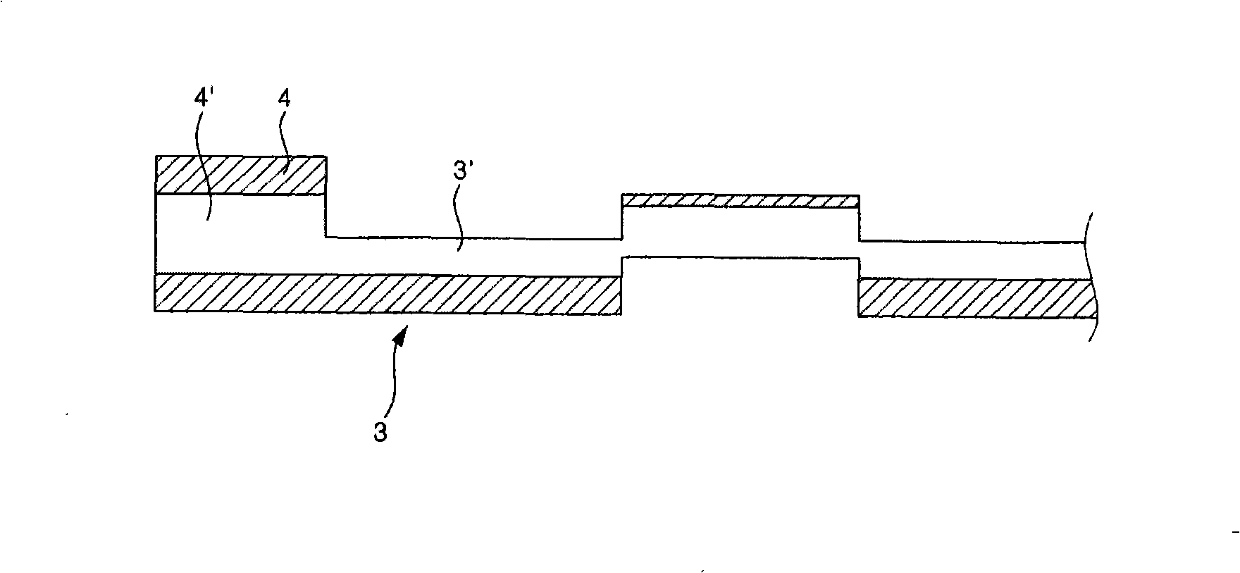
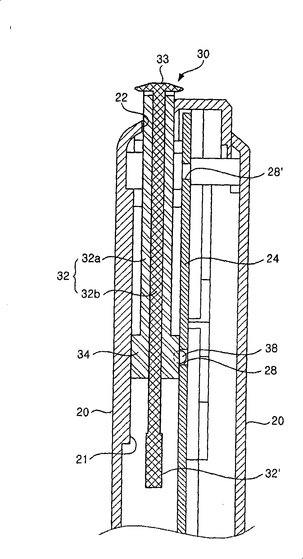
[0046] image 3 It is a schematic cross-sectional view of the composition of the preferred embodiment of the antenna structure according to the present invention. Figure 4 It is an exploded perspective view of the main parts of the embodiment of the present invention. Figure 5 It is a perspective view of the antenna structure of the embodiment of the present invention.

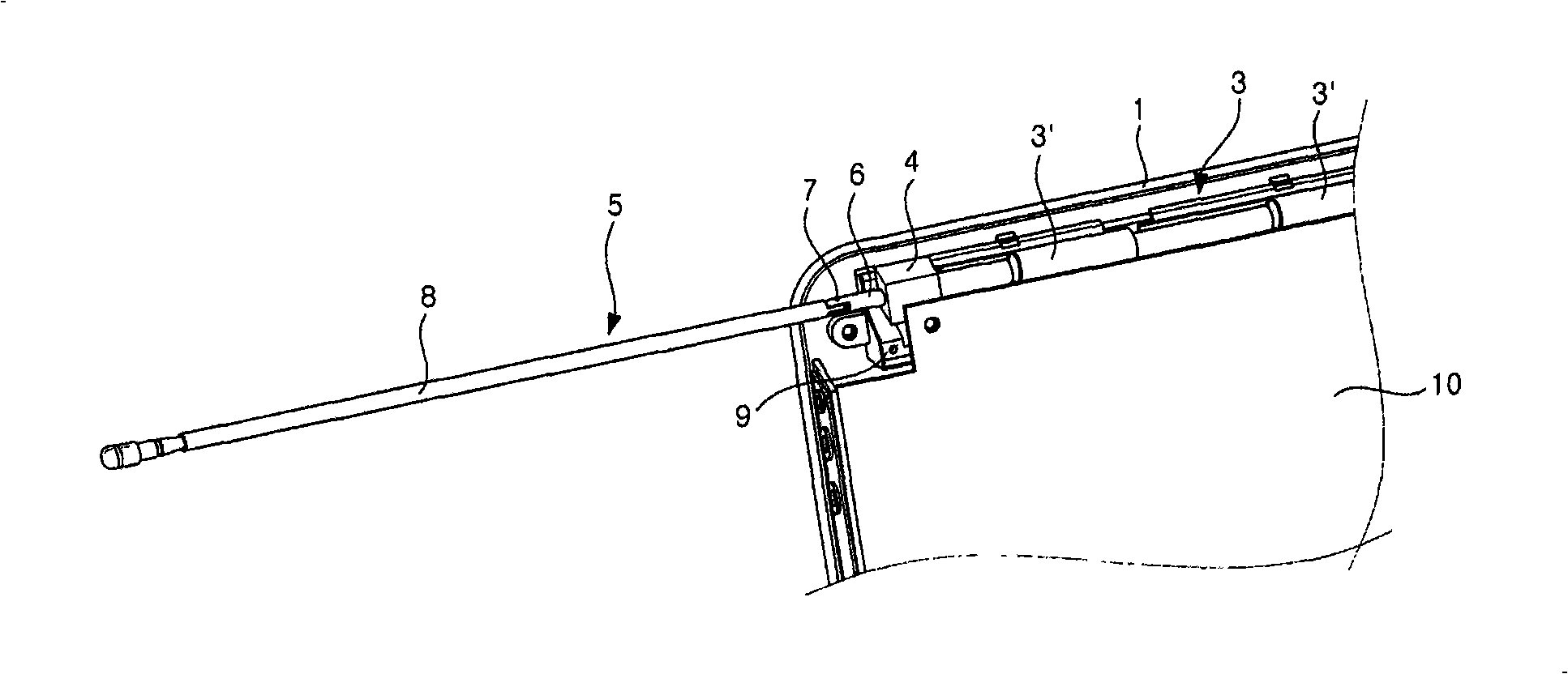
[0047] As shown in the drawings, the casing 20 forms the appearance of the mobile device product, and a predetermined space is formed inside it for arranging various components constituting the mobile device. The casing 20 is generally composed of at least two or more parts. For example, the combination of the front cabinet and the rear cabinet constitutes the appearance of the product.

[0048]A guide leg 21 is provided...


PUM


Abstract

The invention relates to an antenna installation structure which comprises a shell that forms the appearance with a specified space inside and a perforation at one side; a substrate located in the inside space formed by the shell with one surface provided with a contact plane formed by extending from the peroration along a direction; an antenna comprising an interconnecting piece of the contact plane that constantly contacts with the contact plane, and an elongation part moving along with the interconnecting piece and going with the contact plane on the substrate to move to the inside or outside from the perforation of the shell for receiving and sending signals; a lead foot correspondingly prolonging along the prolonging direction of the contact plane and leading the interconnecting piece to move. As the antenna is electrically connected with a base unit, the antenna installation structure of the invention can receive and send signals passing through the antenna even if the antenna does not protrude or only protrudes a little part from the shell, which improves the convenience of a user; as the moving path of the antenna is on the base unit, the antenna installation structure of the invention also has the advantage of leading to a smaller shell on the whole.

Description

technical field [0001] The present invention relates to an antenna, in particular to an antenna mounting structure for an antenna mounted on a device for sending and receiving signals for digital multimedia broadcasting. Background technique [0002] Recently, with the increasing use of mobile devices, the importance of antennas for transmitting and receiving wireless signals has become increasingly prominent. In particular, in order to be able to watch Digital Multimedia Broadcasting (DMB) through mobile devices, the necessity of an antenna has become greater. [0003] figure 1 Shown is an antenna mounting structure according to the prior art, figure 2 Shown is a schematic cross-sectional view of important parts of a mounting frame constituting an antenna structure according to the prior art. [0004] Accordingly, the mounting frame 3 is fixed inside the casing 1 constituting the appearance of the product. The installation frame 3 sets the antenna 5 inside the casing 1...

Claims


Application Information

Patent Timeline
Patent Type & Authority Applications(China)
IPC IPC(8): H01Q1/12H01Q1/22
Inventor 权成永
Owner LEJIN ELECTRONICS KUNSHAN COMPUTER CO LTD
Why Eureka
Try Eureka