Direct plug-in element with integrated locking mechanism

a technology of locking mechanism and plug-in element, which is applied in the direction of coupling device connection, coupling device details, coupling device engagement/disengagement, etc., can solve the problems of high design cost of direct plug-in element, and achieve cost-efficient and economic mass production of components, reduce the number of components, and withstand higher loads

Active Publication Date: 2014-07-31
ROBERT BOSCH GMBH
View PDF7 Cites 0 Cited by
  • Summary
  • Abstract
  • Description
  • Claims
  • Application Information

AI Technical Summary

Benefits of technology

[0003]The advantage of the direct plug-in element of the invention is that no additional components are necessary on a counterpart to generate the contact force and a direct contact is self-latching. Consequently, a simply constructed direct plug-in element with an integrated locking mechanism is provided. This is achieved by the invention in that the direct plug-in element comprises a plug housing and a direct contact having a contact tongue, wherein the contact tongue has at least one contact portion for directly contacting an exposed contact region on a counterpart. In addition, a latching mechanism is provided between the plug housing and the direct contact in order to keep the direct contact, which is arranged in the plug housing, in the plug housing. The latching mechanism has a first latching element on the direct contact, which is set up in order to enter into a latching connection with a second latching element, which is formed in a complementary manner to the first latching element, on the plug housing. In this connection, the first latching element is arranged on a flat side of the direct contact and the contact portion is arranged on one of the narrow sides of the contact tongue. Provided as a result is a direct plug-in element with a latching mechanism which enables automatic latching of the direct contact with the plug housing by virtue of the respective inherent forms of the same. Cost-efficient and economic mass production of the components is achieved as a result of the minimized number of components. The contact tongue of the invention consequently has a very flexible spring function as the contact tongue can be long in length, preferably more than half, in a particularly preferred manner more than ¾ of an overall length of the direct plug-in element. In this case, the contact tongue of the invention is very sturdy and can also withstand higher loads. This is a considerable advantage in particular in the case of miniaturized contacts.

Problems solved by technology

Up to now, the design of direct plug-in elements has been expensive where direct contacts are pressed onto a counterpart or are latched in a plug housing by means of additional components.

Method used


Image

  • Direct plug-in element with integrated locking mechanism
  • Direct plug-in element with integrated locking mechanism
  • Direct plug-in element with integrated locking mechanism

Examples


Embodiment Construction

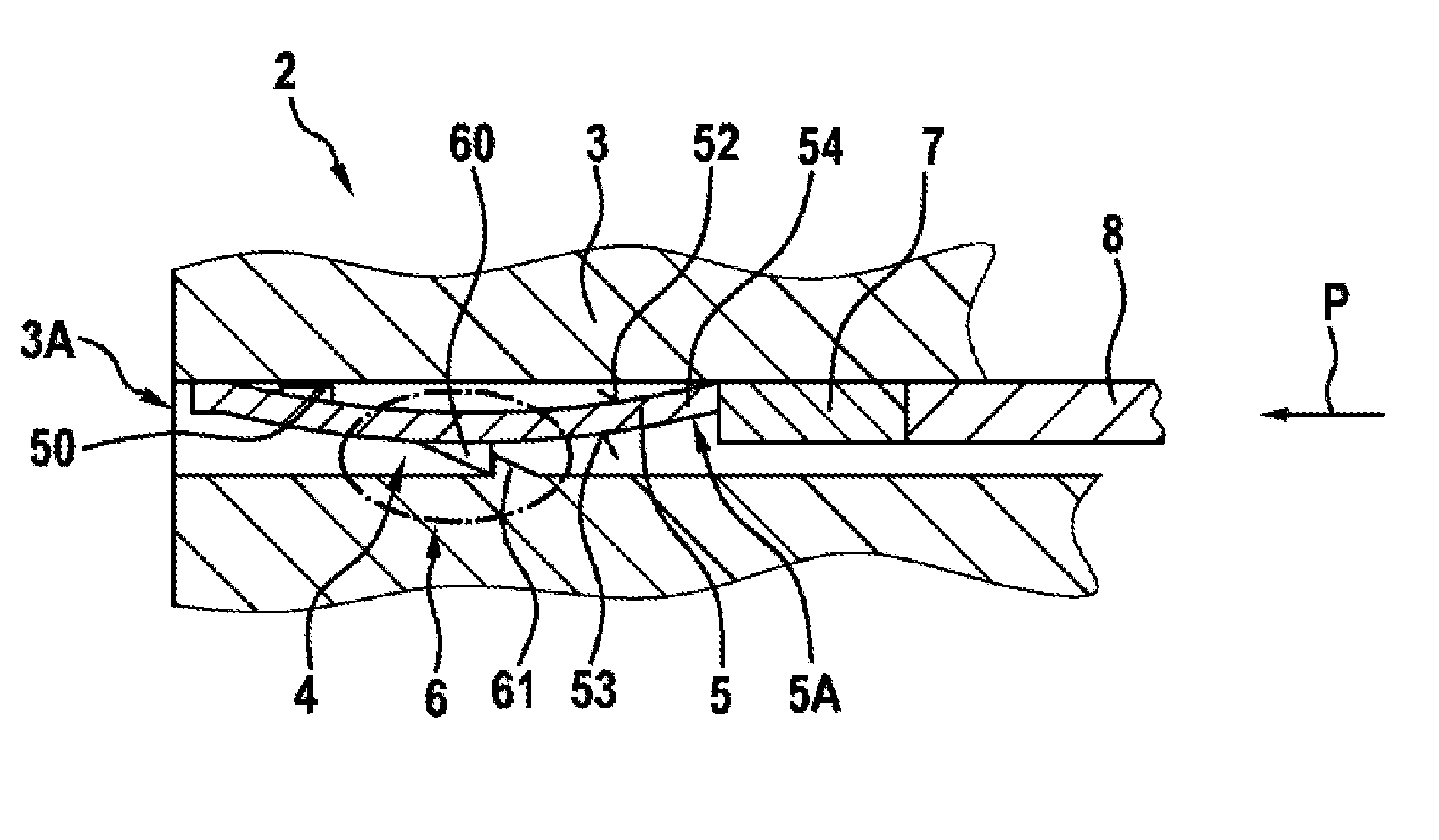
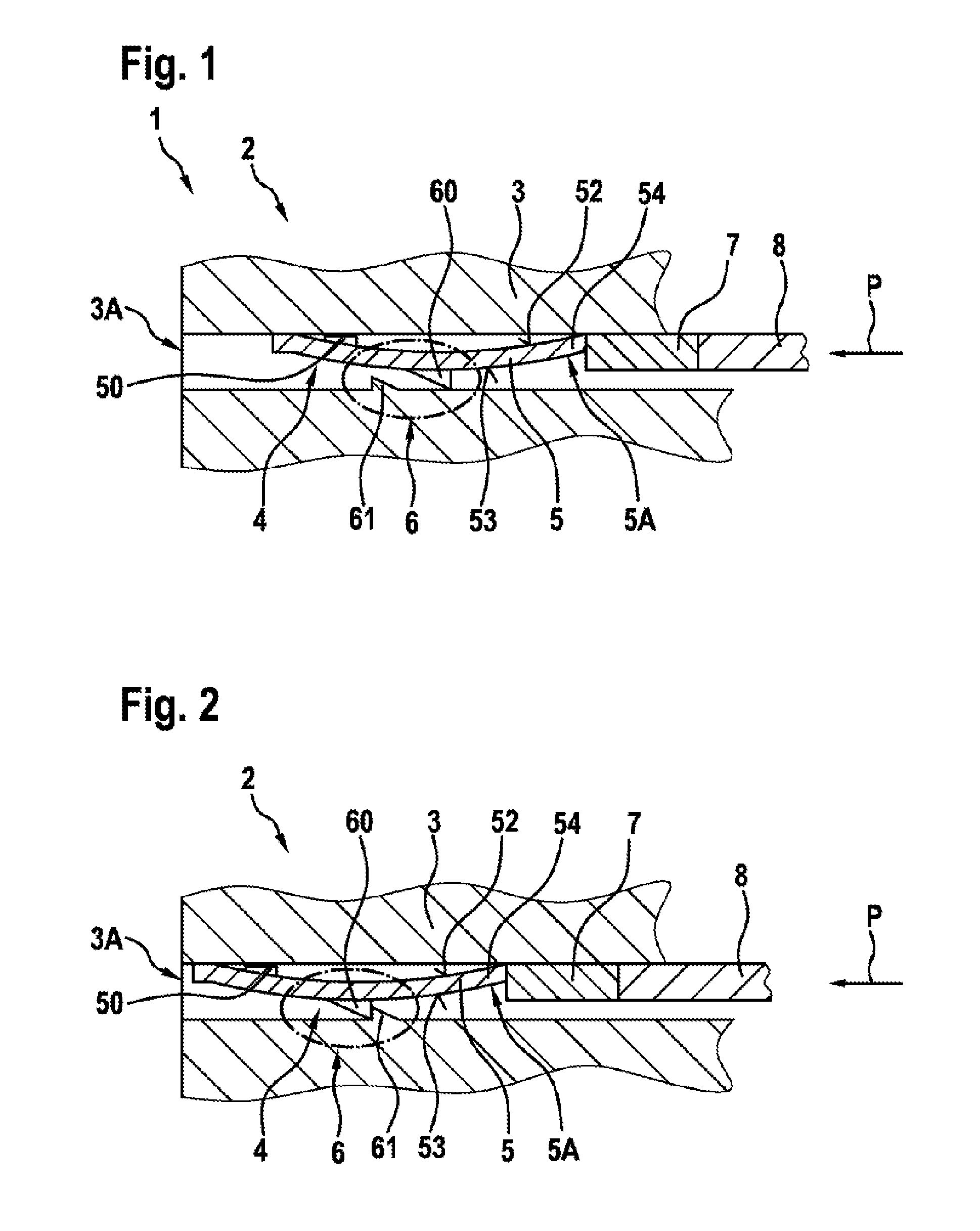
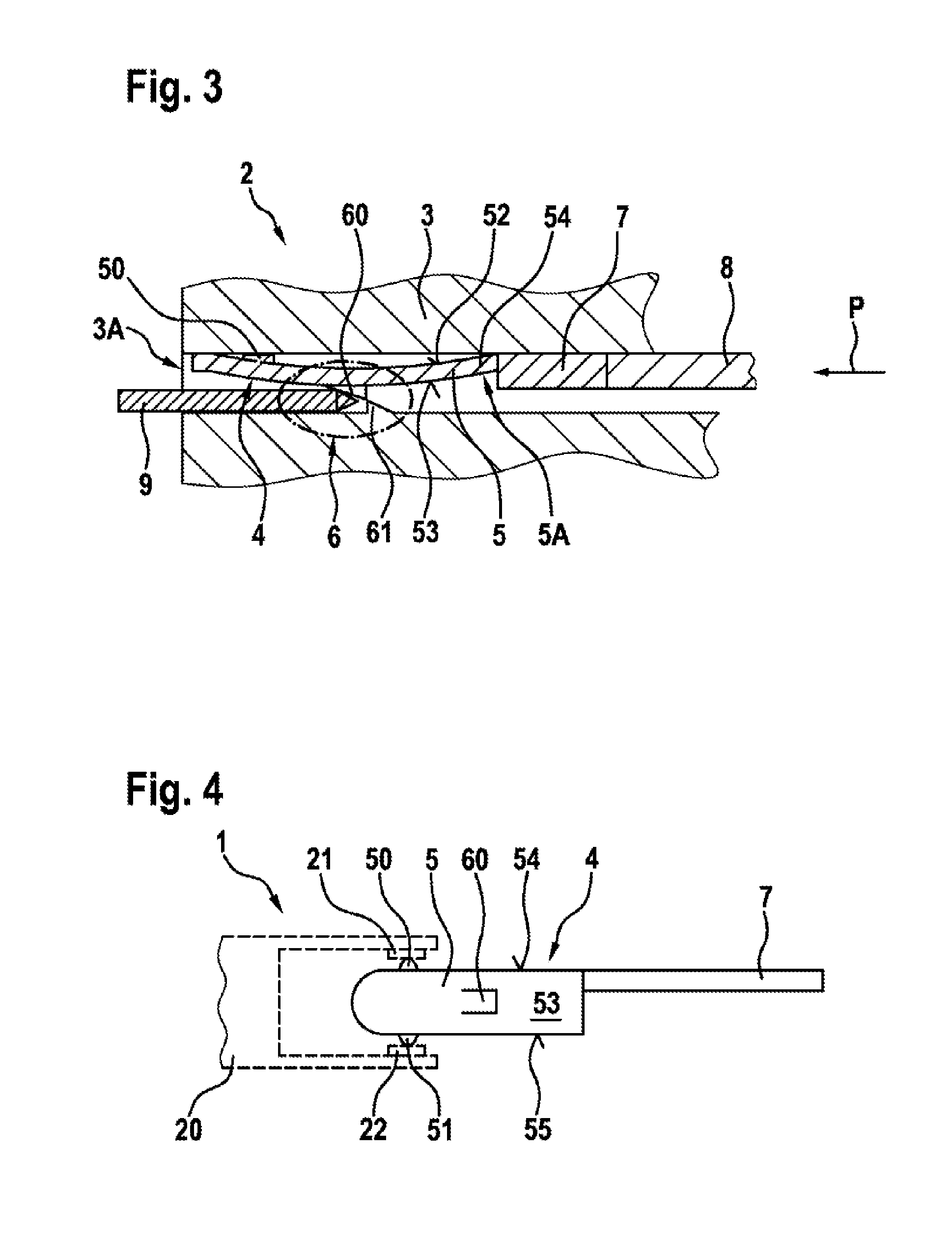
[0023]A direct plug-in element 2 of a preferred exemplary embodiment of the invention is described in detail below with reference to FIGS. 1 to 7.

[0024]As can be seen from FIG. 1, the direct plug-in element 2 includes a plug housing 3 and a direct contact 4 which is arranged in the plug housing 3. In addition, a latching mechanism 6 is provided for a latching connection between the plug housing 3 and the direct contact 4 in order to keep the direct contact 4 in the plug housing 3. The direct contact 4 has a curved contact tongue 5 which has resilient characteristics and is connected to a cable 8 by means of a fastening portion 7. The contact tongue 5 has first and second flat sides 52 and 53 (see FIG. 6) as well as first and second narrow sides 54, 55 (see FIG. 4). The latching mechanism 6 has a first latching element 60 which is arranged on the second flat side 53 on a convex region 5A of the curved contact tongue 5 (as is also illustrated in FIG. 5). The latching element 60, in th...


PUM

PropertyMeasurementUnit
angleaaaaaaaaaa
anglesaaaaaaaaaa
resilient characteristicsaaaaaaaaaa

Abstract

The invention relates to a direct plug-in element comprising: a plug housing (3), a direct contact (4) with a contact tongue (5), the contact tongue (5) having at least one contact section (50) for directly contacting an exposed contact area on a counterpart, and a catch device (6) for an interlocked connection between the plug housing (3) and the direct contact (4), in order to retain the direct contact (4) in the plug housing (3), the direct contact (4) being arranged in the plug housing (3), the contact tongue (5) having a first and second flat side (52, 53) and a first and second narrow side (54, 55), the catch device (6) comprising a first catch element (60) on the direct contact (4) and a second catch element (61) formed on the plug housing (3) complementary to the first catch element (60), the first catch element (60) being arranged on one of the flat sides (52, 53) of the direct contact (4), and the contact section (50) being arranged on one of the narrow sides (54, 55)of the contact tongue (5).

Description

BACKGROUND OF THE INVENTION[0001]The present invention relates to a direct plug-in element with a plug housing and a direct contact for directly contacting exposed contact regions on a counterpart, for example a printed circuit board, as well as to an electric arrangement with a direct plug-in element of this type.[0002]Recently, more and more direct plug-in contacts are used where a direct plug-in element is plugged directly onto a counterpart, such as, for example, a printed circuit board or a pressed screen or substrate. In particular when used in the area of vehicles, however, there are increased demands with regard to a ruggedness and contact reliability of these types of direct plug-in connections. Up to now, the design of direct plug-in elements has been expensive where direct contacts are pressed onto a counterpart or are latched in a plug housing by means of additional components. It is desirable, however, in particular in the case of mass produced products such as, for exa...

Claims


Application Information

Patent Timeline
Patent Type & Authority Applications(United States)
IPC IPC(8): H01R13/62H01R43/26
CPCH01R43/26H01R13/62H01R13/428Y10T29/49224
Inventor KROECKEL, MARKUS
Owner ROBERT BOSCH GMBH
Why Eureka
Try Eureka