Electronic component supply system

a technology of electronic components and supply systems, applied in the direction of electrical components, electrical apparatus, etc., can solve the problems of increasing work man-hours, complex steps, and not taking into account the number of component pallets to be prepared, so as to improve the operating ratio of the electronic component mounting machine, simplify the preparation step, and reduce the number of times of the component pallet setup change

Active Publication Date: 2017-12-07
FUJI MASCH MFG CO LTD
View PDF1 Cites 0 Cited by
  • Summary
  • Abstract
  • Description
  • Claims
  • Application Information

AI Technical Summary

Benefits of technology

[0003]PTL 1 minimizes the number of times of the component pallet setup changing and improves the operating ratio of the electronic component mounting machine by adjusting a manufacturing order (grouping the mounting boards that are manufactured). However, PTL 1 does not take the number of the component pallets to be prepared into account. In PTL 1, all of the component pallets are exchanged during switching between the groups of the mounting boards that are manufactured, and thus the number of component pallet exchanges is not at its minimum. For operators preparing the component pallets before the board production, work man-hours increases and steps become complex as the number of the pallets to be prepared each day increases. An object of the present description is to provide an electronic component supply system with which a component pallet preparation step can be simplified compared to the background art.
[0004]An electronic component supply system disclosed in the present description determines the types of electronic components installed on component pallets at a time when the electronic components are installed on the component pallets. The electronic component supply system determines the types of the electronic components installed on the component pallets based on planned multiple jobs continuously performed by multiple electronic component mounting machines to which the component pallets are attached and an execution order for the jobs such that the number of the component pallets exchanged during job switching is minimized.
[0005]The control device described above determines the types of the electronic components installed on the component pallets based on the multiple jobs and the execution order for the jobs such that the number of the component pallets exchanged during the job switching is minimized. A component pallet preparation step can be simplified based on the minimization of the number of the exchanged component pallets.

Problems solved by technology

However, PTL 1 does not take the number of the component pallets to be prepared into account.
For operators preparing the component pallets before the board production, work man-hours increases and steps become complex as the number of the pallets to be prepared each day increases.

Method used


Image

  • Electronic component supply system
  • Electronic component supply system
  • Electronic component supply system

Examples


embodiment

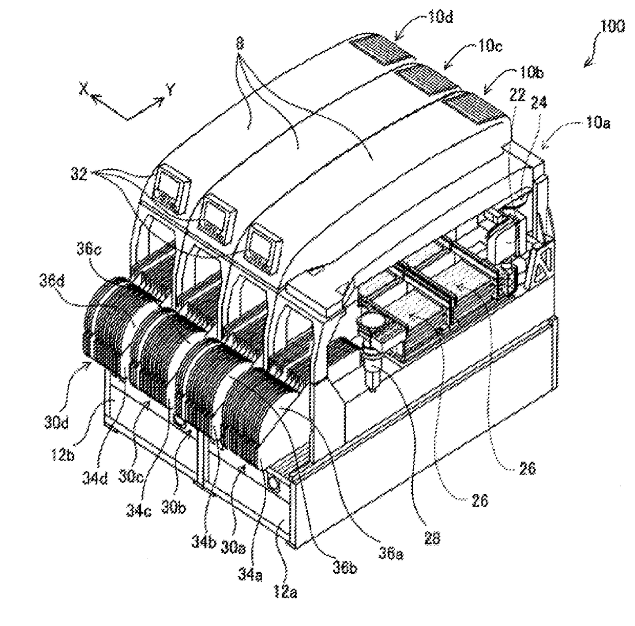
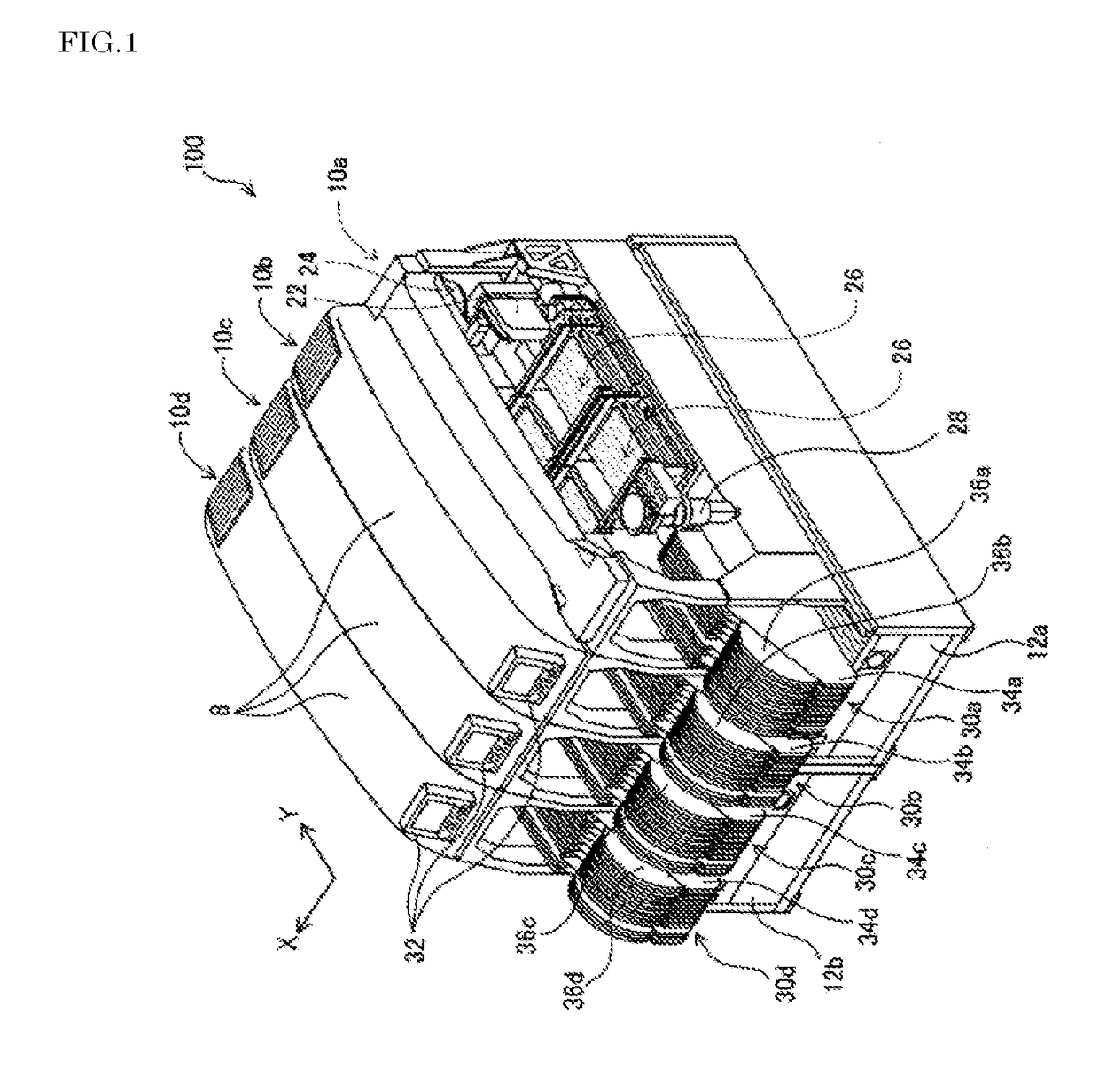
[0014]Hereinafter, the electronic component supply system disclosed in the present description and the electronic component mounting machines used in the electronic component supply system will be described with reference to accompanying drawings. An electronic component mounting system 100 will be described first with reference to FIG. 1. The electronic component mounting system 100 is provided with four electronic component mounting machines 10a, 10b, 10c, and 10d. Each of the electronic component mounting machines 10a to 10d is a device for mounting an electronic component on a printed circuit board. In some cases, the electronic component mounting machines 10a to 10d (or the electronic component mounting system 100) are referred to as surface mounting machines or chip mounters. in the following description, the direction in which the electronic component mounting machines 10a to 10d line up will be referred to as an X direction and the horizontal direction that is perpendicular ...


PUM

PropertyMeasurementUnit
timeaaaaaaaaaa
lengths of timeaaaaaaaaaa
timeaaaaaaaaaa

Abstract

Provided is an electronic component supply system determining the types of electronic components installed on component pallets at a time when the electronic components are installed on the component pallets for installation, which determines the types of the electronic components installed on the component pallets based on planned multiple jobs continuously performed by multiple electronic component mounting machines to which the component pallets are attached and an execution order for the jobs such that the number of the component pallets exchanged during job switching is minimized.

Description

TECHNICAL FIELD[0001]The present description relates to an electronic component supply system. More particularly, the present description relates to a system that supplies electronic components to an electronic component mounting machine by exchanging component pallets where multiple component cartridges accommodating electronic components are installed.BACKGROUND ART[0002]JP-A-4-346500 (hereinafter, referred to as PTL 1) discloses a supply system that supplies an electronic component mounting machine with component pallets at a time when multiple types of mounting boards are manufactured. Multiple component cartridges can be installed on the component pallets according to PTL 1. PTL 1 specifies the types of electronic components mounted on the mounting boards that are manufactured and groups the mounting boards that are manufactured by itself such that the manufacturing can be performed by the same component pallets being used. In other words, PTL 1 groups the mounting boards that ...

Claims


Application Information

Patent Timeline
Patent Type & Authority Applications(United States)
IPC IPC(8): H05K13/02H05K13/00H05K13/08H05K13/04
CPCH05K13/02H05K13/04H05K13/0084H05K13/08H05K13/085H05K13/0857H05K13/0434H05K13/086Y10T29/53174
Inventor YAMASHITA, YUKIHIROMURATSUCHI, HIROAKI
Owner FUJI MASCH MFG CO LTD
Why Eureka
Try Eureka