Multi-spindle head exchangeable machine tool

a machine tool and spindle head technology, applied in the direction of driving apparatus, manufacturing tools, transportation and packaging, etc., can solve the problems of difficult detachment of gang heads and difficult to achieve high speed rotation of tools, and achieve the effect of improving the operating ratio

Inactive Publication Date: 2009-03-26
HONDA MOTOR CO LTD
View PDF4 Cites 1 Cited by
  • Summary
  • Abstract
  • Description
  • Claims
  • Application Information

AI Technical Summary

Benefits of technology

[0015]One or more embodiments of the present invention provide a multi-spindle head exchangeable machine tool which can perform maintenance such as a tooling change of some multi spindle heads even though another multi spindle heads are in use, and improve an operating ratio thereof; and also provide a moving lock device which can prevent the multi spindle head from moving on a rail supporting the multi spindle head.

Problems solved by technology

Thus, it is difficult to detach the gang heads 42b to 42d, which are relatively heavy, in such a too short time for the tooling change.
Further, it is difficult to achieve the high speed rotation of the tool.

Method used


Image

  • Multi-spindle head exchangeable machine tool
  • Multi-spindle head exchangeable machine tool
  • Multi-spindle head exchangeable machine tool

Examples


Embodiment Construction

[0111]Exemplary embodiments of the invention will be described with reference to the accompanying drawings.

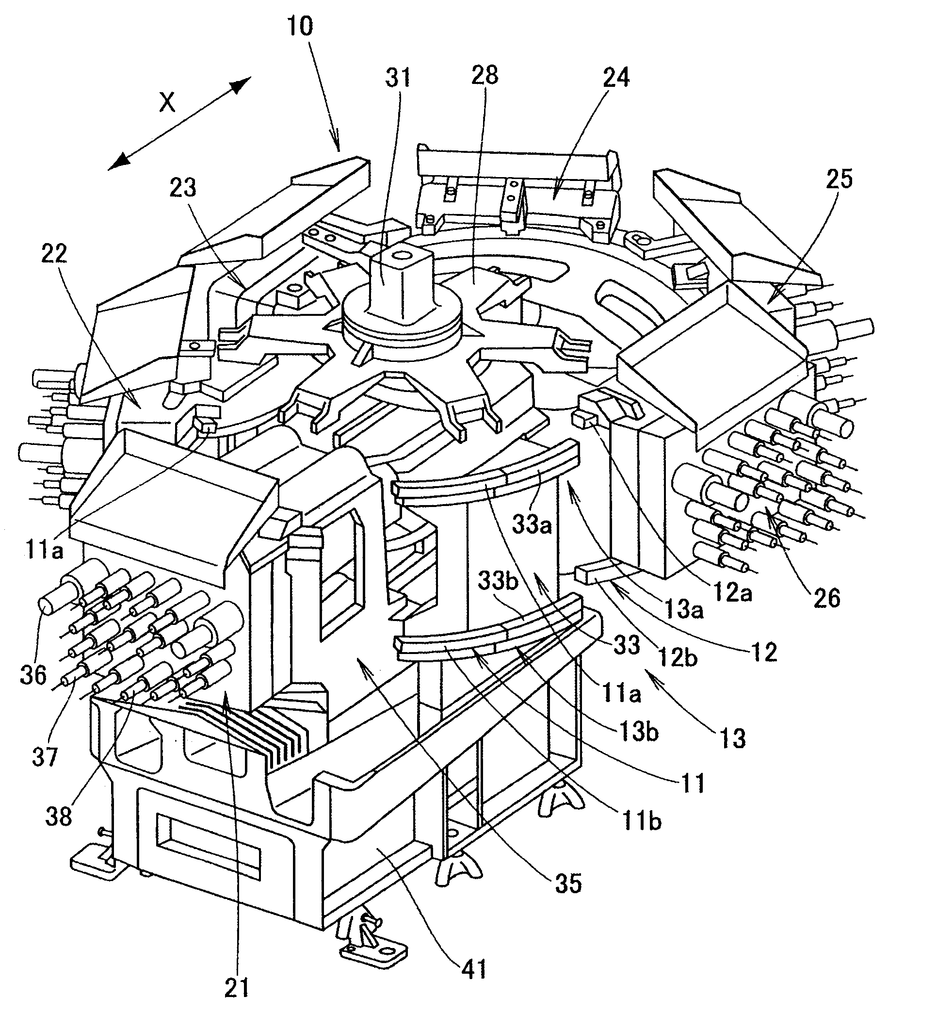
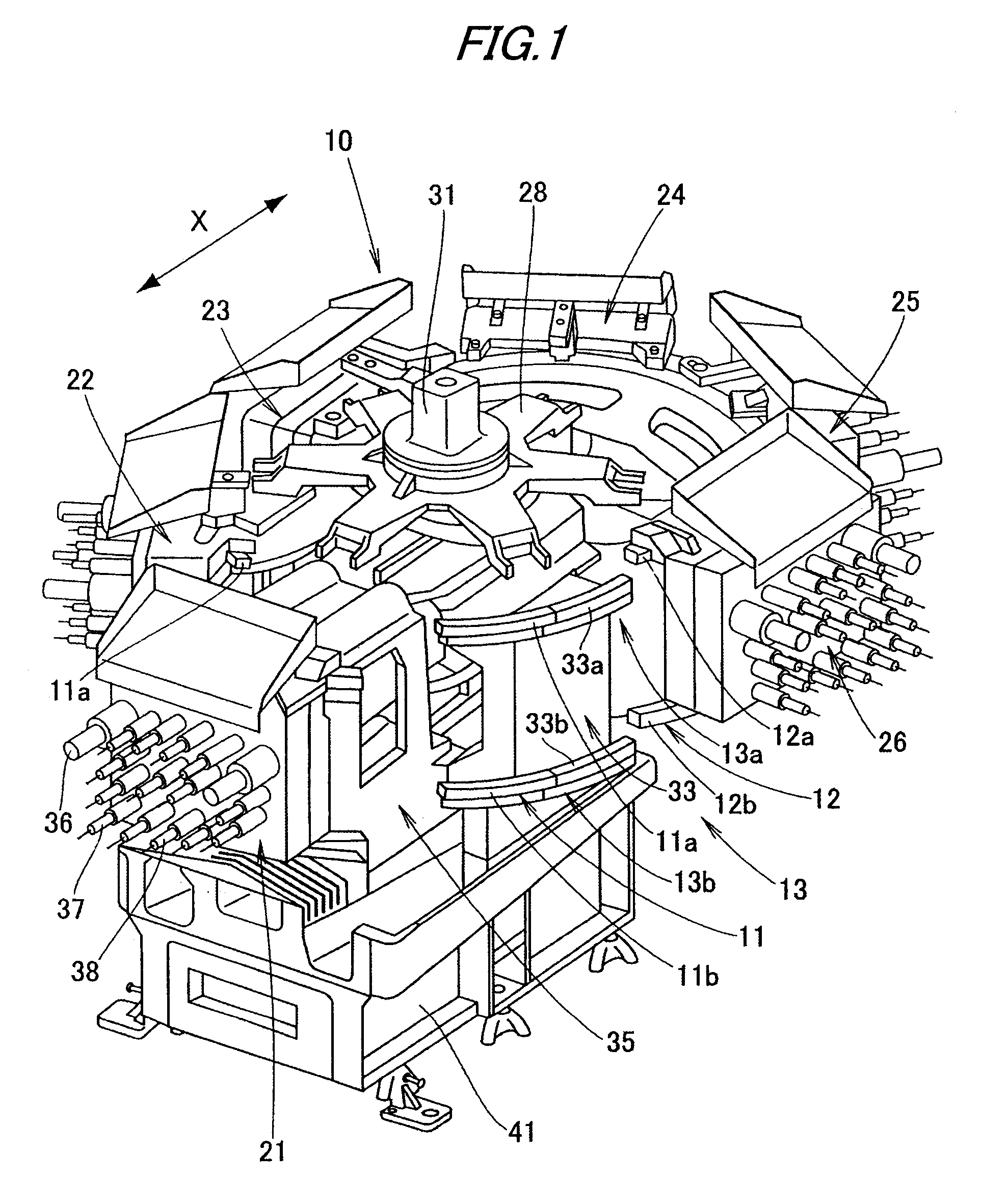
[0112]It is preferable that the drawings be seen on the basis of a direction of reference numerals. FIG. 1 is a perspective view of a multi-spindle head exchangeable machine tool according to an exemplary embodiment of the invention. In the multi-spindle head exchangeable machine tool 10, a plurality of multi spindle heads (so-called “gang head”) 21 to 26 is movably mounted to an annular rail 13, which can be divided into a first stationary rail 11 and a second stationary rail 12 in an X-axis direction. The first stationary rail 11 includes an upper first stationary rail 11a and a lower first stationary rail 11b placed under the upper first stationary rail 11a, and the second stationary rail 12 includes an upper second stationary rail 12a and a lower second stationary rail 12b placed under the upper second stationary rail 12a. Further, the annular rail 13 includes an upper annu...


PUM

PropertyMeasurementUnit
timeaaaaaaaaaa
timeaaaaaaaaaa
angleaaaaaaaaaa

Abstract

A multi-spindle head exchangeable machine tool is provided with a plurality of multi spindle heads movably mounted on an annular rail. When a workpiece is machined by driving a rotary tool by a machining unit, multi spindle heads of the plurality of multi spindle heads being out of use can be separated from the machining unit.
Further, a connecting device is provided with an inner slider, ball bearings fitted to an outer periphery of the inner slider, an outer slider, and a coil spring to press the outer slider toward a stopper member.

Description

TECHNICAL FIELD[0001]The present invention relates to a multi-spindle head exchangeable machine tool.BACKGROUND ART[0002]There is known a conventional multi-spindle head exchangeable machine tool provided with a plurality of gang heads (multi spindle heads), in which the plurality of gang heads are connected with a index table and moved on an annular rail (for example, refer JP-A-63-114807). In the multi-spindle head exchangeable machine tool, an input shaft of one of the gang heads with rotary tools is detachably mounted to an output shaft of a machining unit.[0003]As shown in FIG. 2 of JP-A-63-114807, in the multi spindle machine tool 30, gang heads 42a to 42d serving as multi spindle heads are movably mounted on upper and lower annular rails 40a and 40b. The gang heads 42a to 42d are engaged to an index table 44 disposed above the annular rail 40a. When a rotary driving source 46 rotates the index table 44, the gang heads 42a to 42d rotates. Thus, one of the gang heads 42a to 42d...

Claims


Application Information

Patent Timeline
Patent Type & Authority Applications(United States)
IPC IPC(8): B23B39/16B23Q3/157B23Q5/04
CPCB23B39/161B23Q3/15706B23Q2210/006Y10T483/1733Y10T483/1795Y10T483/1738Y10T483/1873Y10T483/1818Y10T408/3806Y10T483/1786Y10T483/1783B23Q2003/1558B23B39/16B23Q3/157B23Q5/04
Inventor UCHIKAWA, MOTOKIMIYAGI, TOMOYOSHIHIRAO, NORIFUMIGOTO, KANAMEMOTOJIMA, TAKAYUKI
Owner HONDA MOTOR CO LTD
Why Eureka
Try Eureka