
Manufacturing method, control device, and manufacturing apparatus of optical fiber

a manufacturing apparatus and control device technology, applied in the direction of glass optical fiber, manufacturing tools, instruments, etc., can solve the problems of reducing productivity, reducing the efficiency of manufacturing, so as to improve the efficiency of manufacturing and reduce the cost of manufacturing. , the effect of enhancing productivity

Active Publication Date: 2016-12-01
THE FUJIKURA CABLE WORKS LTD
View PDF2 Cites 2 Cited by
  • Summary
  • Abstract
  • Description
  • Claims
  • Application Information

AI Technical Summary

Benefits of technology

The patent describes a method for manufacturing optical fiber that ensures a consistent and high-quality finished product. The method includes steps to measure the outer diameter of the bare optical fiber and to control the flow rate of fluid introduced into a direction changing device so as to reduce any differences between the target floating position and the detected position of the bare optical fiber. This results in a stable floating position of the bare optical fiber in the direction changing device, ensuring a constant position as the fiber enters the coating unit, and prevents uneven thickness of the coating and produces optical fiber with consistent quality.

Problems solved by technology

The height of the system is the main factor in the restriction of productivity because there is a need to ensure a sufficient distance for cooling the bare optical fiber obtained by drawing of the optical fiber preform.
However, this requires an enormous cost.
Therefore, there is concern that the bare optical fiber may come into contact with the inner surface of the groove of the tool.
When the bare optical fiber comes into contact with the tool, the bare optical fiber is damaged, and there is a possibility that the strength thereof may decrease.
Therefore, there is concern that the bare optical fiber may come into contact with the inner surface of the groove of the tool, the bare optical fiber may be damaged, and the strength thereof may decrease.
In addition, when the floating position of the bare optical fiber is changed in the non-contact holding mechanism, the position of the bare optical fiber introduced into the coating unit provided on the downstream side of the non-contact holding mechanism varies, and there is concern that the thickness of the coating may become uneven.

Method used


Image

  • Manufacturing method, control device, and manufacturing apparatus of optical fiber
  • Manufacturing method, control device, and manufacturing apparatus of optical fiber
  • Manufacturing method, control device, and manufacturing apparatus of optical fiber

Examples


example

Example 1

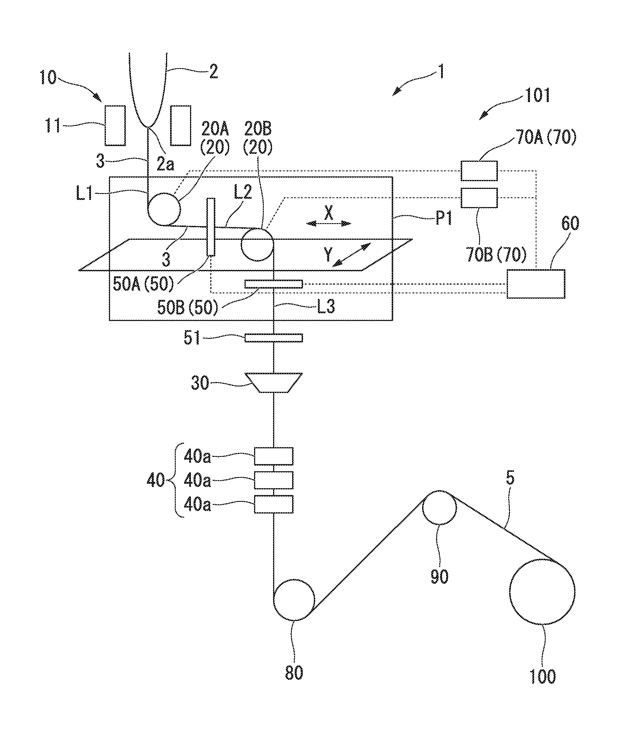
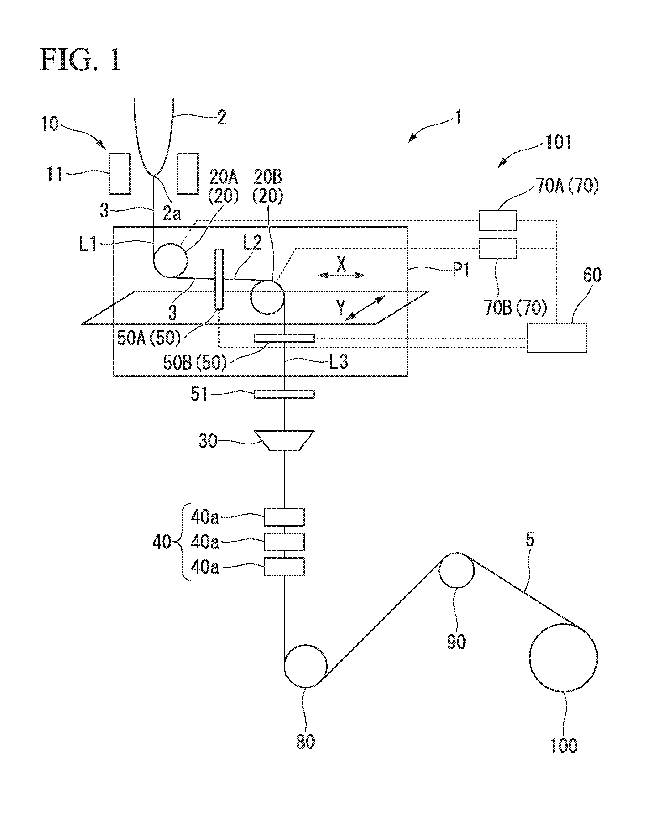
[0130]The manufacturing apparatus 1 shown in FIG. 1 was prepared. As the direction changing devices 20A and 20B, the direction changing device 201 shown in FIG. 3 was used.

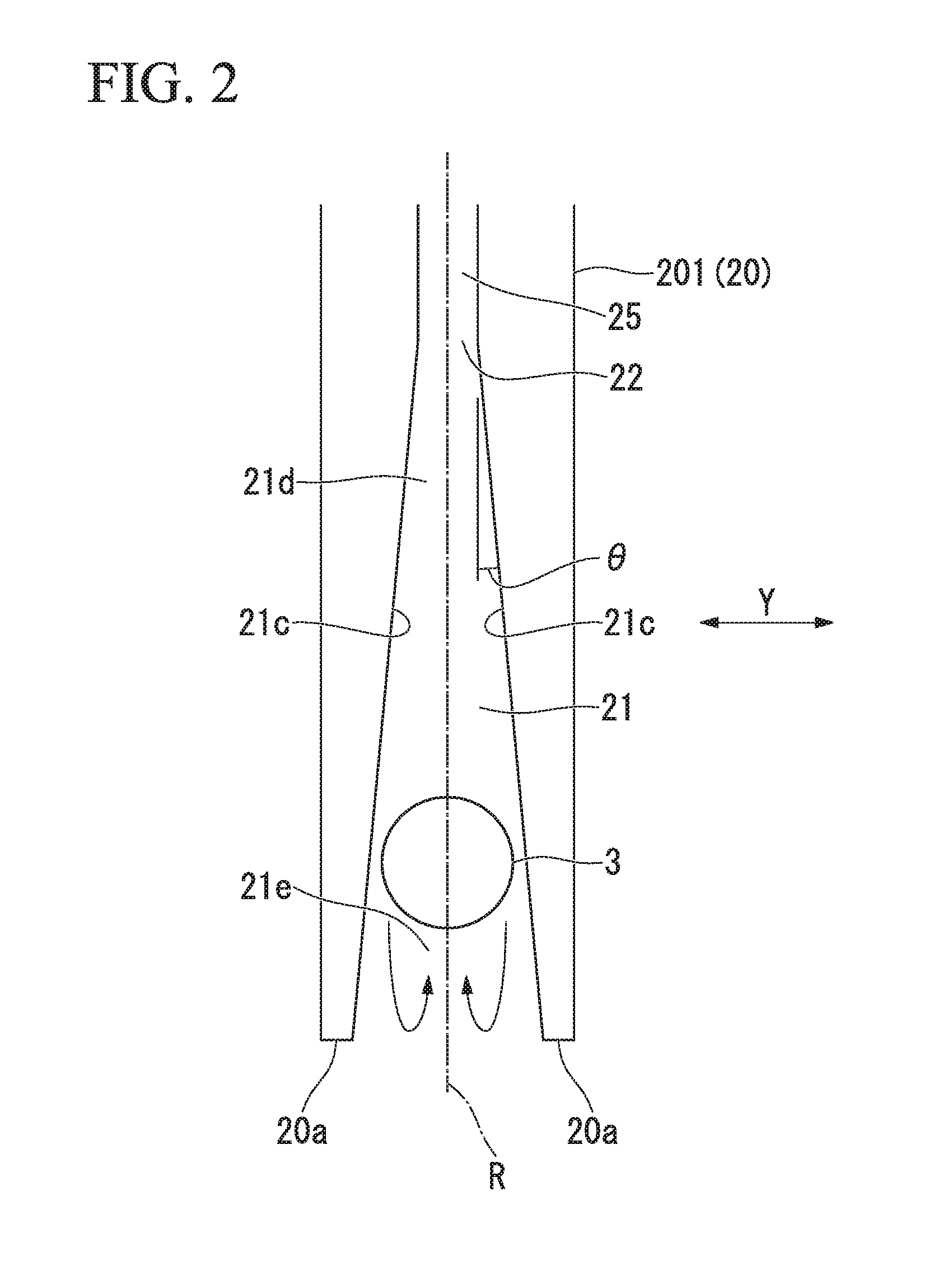
[0131]As shown in FIG. 2, the inclination angle θ of the inner side surface 21c of the guide groove 21 with respect to the radial direction R was set to 0.5°. The width of the bottom of the guide groove 21 was set to 50 μm.

[0132]As the fluid introduced into the direction changing devices 20A and 20B, air was used.

[0133]As a result of a preliminary test, a floating turning radius of the bare optical fiber 3 (with an outer diameter of 125 μm) in a case where the flow rate of the air introduced into each of the direction changing devices 20A and 20B was set to 100 L / min was approximately 62.5 mm. Under this condition, it was confirmed that the floating position was more stable than in a case of another condition. Therefore, this position was determined as the optimal floating position of the bare optical fib...

example 2

[0150]The optical fiber 5 was manufactured in the same manner as in Example 1 except that the above-mentioned target floating position was calculated using Expression (2) instead of Expression (1) in the acceleration process. In Expression (2), a was set to 0.5 [mm]. This value (0.5 [mm]) was determined by a preliminary test as a value which ensured a stable floatation amount, did not degrade floating stability, and had a sufficient margin for a control delay (such as a delay in response described above).

[0151]After the drawing velocity and the outer diameter of the optical fiber reached steady levels, control was performed by using the target floating position calculated using Expression (1).

[0152]As a result of a proof test, it was confirmed that the optical fiber 5 could be manufactured with a good yield without damaging the bare optical fiber 3 in the direction changing devices 20A and 20B.


PUM

PropertyMeasurementUnit
velocityaaaaaaaaaa
lengthaaaaaaaaaa
outer diameter D0aaaaaaaaaa

Abstract

A manufacturing method of an optical fiber includes drawing an optical fiber preform and forming a bare optical fiber, coating an outer circumference of the bare optical fiber with a coating layer including a resin, curing the coating layer and forming an optical fiber by curing the coating layer, and changing a direction of the bare optical fiber using one or a plurality of direction changing devices at any position between a position where the bare optical fiber is formed and a position where the coating is performed. The direction changing device includes a guide groove which guides the bare optical fiber, and an internal space portion into which a fluid is introduced from an outside, and in the guide groove, an outlet through which the fluid in the internal space portion is blown to float the bare optical fiber in the guide groove is formed.

Description

CROSS REFERENCE TO RELATED APPLICATIONS[0001]Priority is claimed on Japanese Patent Application No. 2015-107279, filed on May 27, 2015 the contents of which are incorporated herein by reference.BACKGROUND OF THE INVENTION[0002]Field of the Invention[0003]The present invention relates to a manufacturing method, a control device, and a manufacturing apparatus of an optical fiber.[0004]Description of Related Art[0005]In general, in order to manufacture an optical fiber, a fiber drawing method of drawing an optical fiber vertically downward from an optical fiber preform along a straight path is employed.[0006]For example, in order to manufacture an optical fiber 5 using a manufacturing apparatus shown in FIG. 5, an optical fiber preform 2 is melted by a heating furnace 11 of a drawing unit 10 and a bare optical fiber 3 is drawn vertically downward therefrom through drawing. The bare optical fiber 3 is cooled by a cooling unit 120 and is thereafter provided with a coating layer by a coat...

Claims


Application Information

Patent Timeline
Patent Type & Authority Applications(United States)
IPC IPC(8): C03B37/03C03C25/10G02B6/02
CPCC03B37/032C03C25/106G02B6/02395C03B37/023C03B37/075C03C25/285C03B37/0253C03B2205/40Y02P40/57G02B6/00
Inventor OKADA, KENJI
Owner THE FUJIKURA CABLE WORKS LTD
Learn More