Constant current light emitting diode (LED) driver circuit and method

a technology of light emitting diodes and driver circuits, applied in the field of lighting systems, can solve the problems of increasing the size and cost of the drive circuits

Inactive Publication Date: 2011-05-17
INTERSIL INC
View PDF8 Cites 93 Cited by
  • Summary
  • Abstract
  • Description
  • Claims
  • Application Information

AI Technical Summary

Benefits of technology

[0010]According to one embodiment of the present invention, a drive circuit supplies a drive current to a plurality of light emitting diodes. The drive circuit includes a voltage converter circuit having a particular topology and including at least one inductive element and at least one switching element. The drive circuit sense

Problems solved by technology

The current transducer 106 increases the parts count of the Buck converter

Method used


Image

  • Constant current light emitting diode (LED) driver circuit and method
  • Constant current light emitting diode (LED) driver circuit and method
  • Constant current light emitting diode (LED) driver circuit and method

Examples


Embodiment Construction

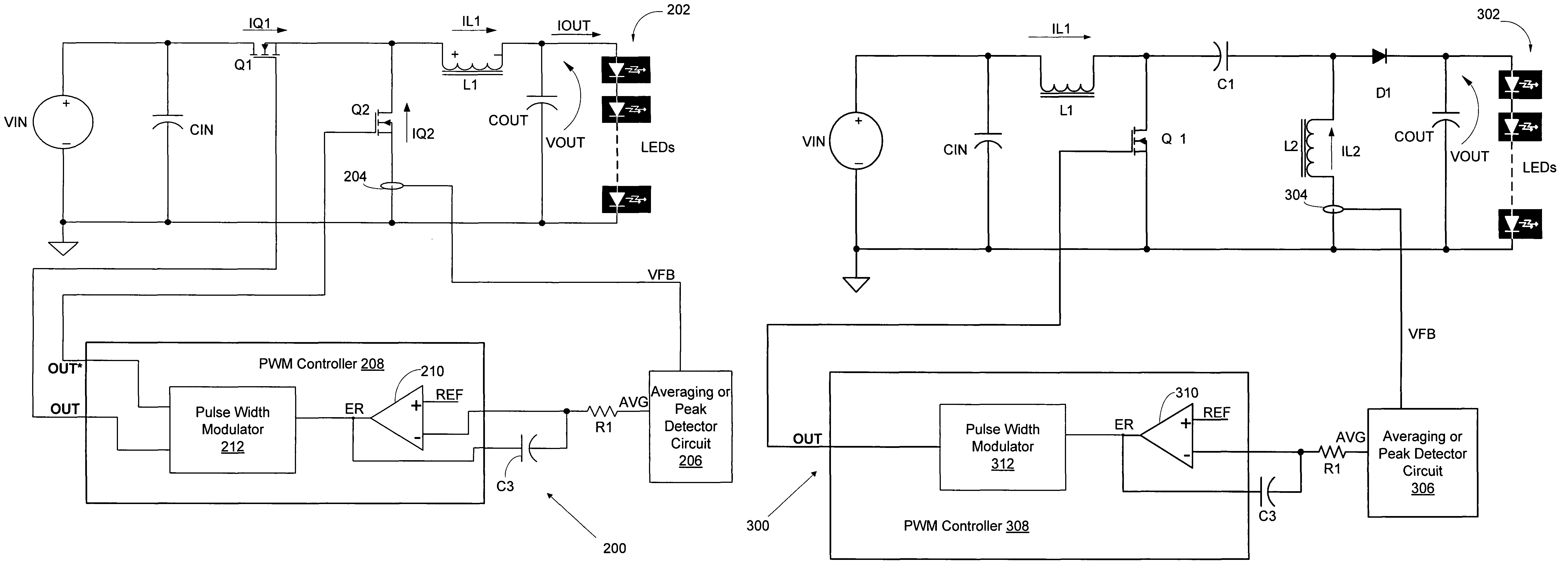
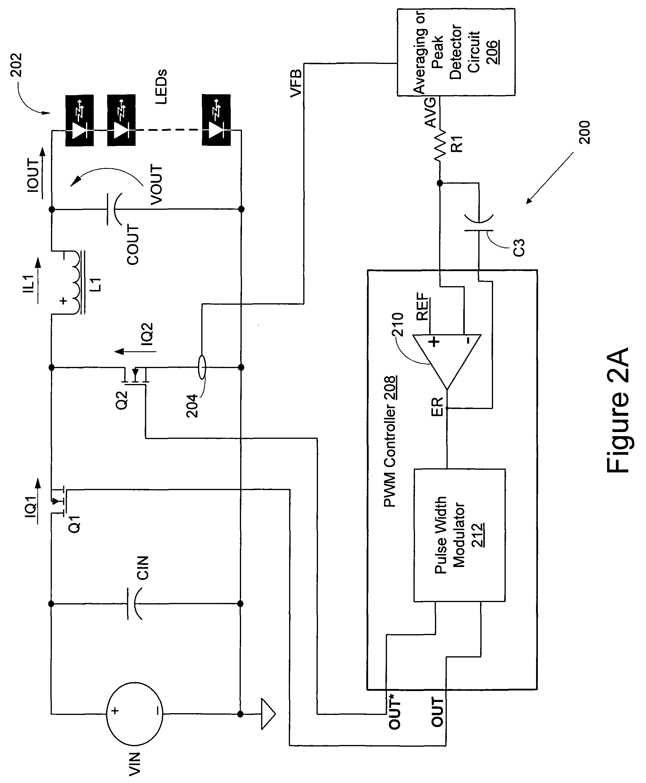
[0023]FIG. 2A is a circuit diagram illustrating a Buck-type drive circuit 200 for driving a number of series-connected LEDs 202 according to one embodiment of the present invention. The converter 200 includes first and second switching transistors Q1 and Q2 and a current transducer 204 coupled in series with the second switching transistor Q2 to generate a voltage feedback signal VFB having a value that is a function of a current IQ2 flowing through a second switching transistor. Because the current IQ2 has a value that is functionally related to the value of a drive, load or output current IOUT flowing through the series-connected LEDs 202, the current IQ2 may be utilized to control the output current IOUT flowing through the LEDs 202, as will be explained in more detail below. Using the current IQ2 enables the drive circuit 200 to control the LEDs 202 through pulse width modulation (PWM) techniques without direct measurement of the output current IOUT through the LEDs, as will als...


PUM


Abstract

A drive circuit supplies a drive current to a plurality of light emitting diodes. The drive circuit includes a voltage converter circuit having a particular topology and including at least one inductive element and at least one switching element. The drive circuit senses a current through one of the inductive and switching elements and generates a feedback signal from the sensed current. The feedback signal has a value indicating the drive current being supplied to the light emitting diodes and the drive circuit controls the operation of the voltage converter responsive to the feedback signal.

Description

PRIORITY CLAIM[0001]The present application claims the benefit of U.S. Provisional Patent Application No. 60 / 875,075, filed Dec. 15, 2006, which application is incorporated herein by reference in its entirety.TECHNICAL FIELD[0002]The present invention relates generally to lighting systems, and more specifically to light emitting diode (LED) lighting systems.BACKGROUND[0003]Light emitting diodes (LED) have reached performance levels that enable such LEDs to be utilized in applications that were not previously possible, such as industrial and consumer lighting applications in which incandescent and fluorescent lighting systems have typically been utilized for many years. When used in these industrial and consumer applications, LED lighting systems ideally will be easily interchangeable with these prior lighting systems to gain acceptance and utilization in these types of applications. For example, these prior lighting systems receive power from alternating current (AC) power sources a...

Claims


Application Information

Patent Timeline
IPC IPC(8): G05F1/00
CPCH05B33/0851H05B33/0818H05B45/3725H05B45/375H05B45/38H05B31/50
Inventor GREENFELD, FRED
Owner INTERSIL INC
Why Eureka
Try Eureka