Apparatus for energy transfer using converter and method of manufacturing same

a technology of converters and accessories, applied in the direction of electric energy management, dc-ac conversion without reversal, battery arrangement for several simultaneous batteries, etc., can solve the problems of adding cost and weight to the vehicl

Active Publication Date: 2010-04-22
GENERAL ELECTRIC CO
View PDF8 Cites 106 Cited by
  • Summary
  • Abstract
  • Description
  • Claims
  • Application Information

AI Technical Summary

Benefits of technology

[0007]In accordance with another aspect of the invention, a method of manufacturing that includes providing a first energy storage device, coupling a first bi-directional buck / boost converter to the first energy storage device, and coupling an input device to the first bi-directional buck / boost converter. The input device is configured to receive electrical energy from an external energy source. The method further includes coupling one or more coupling devices to the first bi-directional buck / boost converter, to the first energy storage device, and to the input device, the one or more coupling devices configured to cause electrical energy to charge the first energy storage device via the first bi-directional buck / boost converter, and configured to cause electrical energy from the first energy storage device to transfer to the voltage inverter via the first bi-directional buck / boost converter.

Problems solved by technology

These additional components which are not generally used during vehicle operation add cost and weight to the vehicle.

Method used


Image

  • Apparatus for energy transfer using converter and method of manufacturing same
  • Apparatus for energy transfer using converter and method of manufacturing same
  • Apparatus for energy transfer using converter and method of manufacturing same

Examples


Embodiment Construction

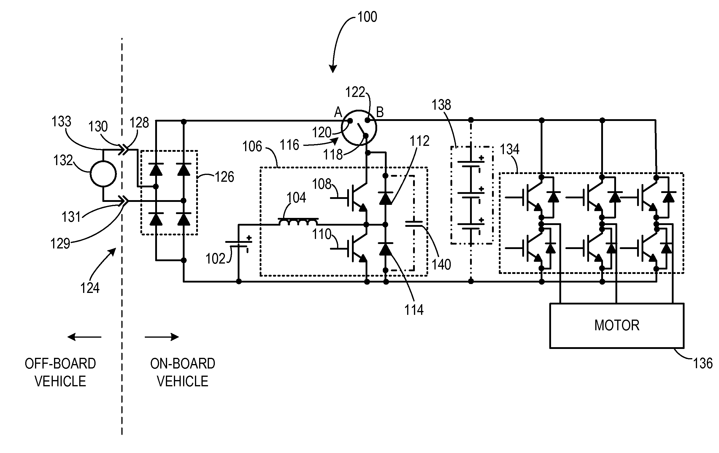
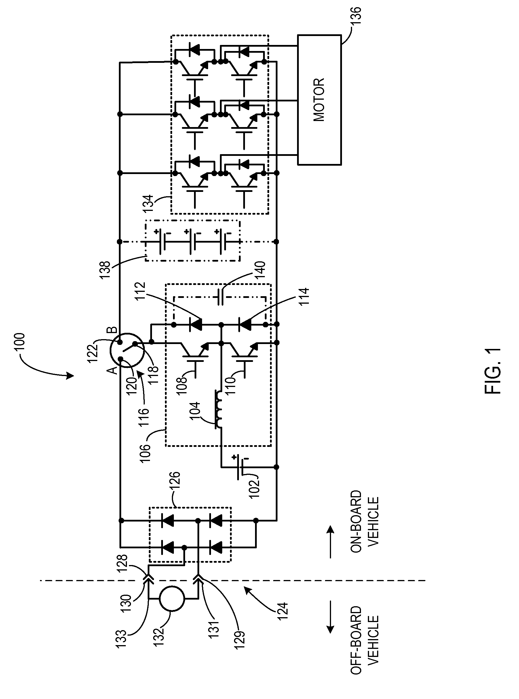
[0021]In an embodiment of the invention illustrated in FIG. 1, a traction system 100 usable in a vehicle, such as a plug-in electric or plug-in hybrid vehicle, or stationary electric drive system is shown. Traction system 100 includes a first energy storage device 102, which may be a battery, a fuel cell, an ultracapacitor, or the like, coupled to an inductor 104 of a bi-directional DC-to-DC voltage converter 106. Inductor 104 is coupled to a first transistor 108 and a second transistor 110 connected in series. Each of the transistors 108, 110 is coupled in anti-parallel with a first and second diode 112, 114, respectively. A coupling system 116 includes a switch 118, which may be, for example, a contactor, a relay, a semiconductor switch, or the like. Switch 118 has a first position 120 and a second position 122 that is coupled to first transistor 108. When switch 118 is in first position 120, bi-directional DC-to-DC voltage converter 106 is coupled to an input device 124, which in...


PUM

PropertyMeasurementUnit
voltageaaaaaaaaaa
voltageaaaaaaaaaa
electrical energyaaaaaaaaaa

Abstract

According to an aspect of the invention, a motor drive circuit includes a first energy storage device configured to supply electrical energy, a bi-directional DC-to-DC voltage converter coupled to the first energy storage device, a voltage inverter coupled to the bi-directional DC-to-DC voltage converter, and an input device configured to receive electrical energy from an external energy source. The motor drive circuit further includes a coupling system coupled to the input device, to the first energy storage device, and to the bi-directional DC-to-DC voltage converter. The coupling system has a first configuration configured to transfer electrical energy to the first energy storage device via the bi-directional DC-to-DC voltage converter, and has a second configuration configured to transfer electrical energy from the first energy storage device to the voltage inverter via the bi-directional DC-to-DC voltage converter.

Description

BACKGROUND OF THE INVENTION[0001]The invention relates generally to hybrid and electric vehicles, and more specifically to systems for charging the energy storage devices used for powering hybrid and electric vehicles.[0002]Hybrid electric vehicles combine an internal combustion engine and an electric motor that is typically powered by an energy storage device, such as a traction battery. Such a combination may increase overall fuel efficiency by enabling the combustion engine and the electric motor to each operate in respective ranges of increased efficiency. Electric motors, for example, may be efficient at accelerating from a standing start, while combustion engines may be efficient during sustained periods of constant engine operation, such as in highway driving. Having an electric motor to boost initial acceleration allows combustion engines in hybrid vehicles to be smaller and more fuel efficient.[0003]Purely electric vehicles typically use stored electrical energy to power an...

Claims


Application Information

Patent Timeline
Patent Type & Authority Applications(United States)
IPC IPC(8): H02J7/10H02P6/00B60L11/18H01G11/00H01G11/10H01M8/00H01M10/44H02J7/00H02M3/155H02M7/48H02P27/06
CPCB60L11/1803Y10T29/49117B60L11/185B60L2210/12B60L2210/14B60L2210/20Y02T10/7005Y02T10/7088Y02T10/7225Y02T10/7233Y02T10/725Y02T90/121Y02T90/127Y02T90/128Y02T90/14B60L11/1818B60L53/24Y10S903/903B60L53/22H02M3/155H02J7/0045H02J7/342B60L53/00B60L53/14B60L53/56Y02T10/92Y02T10/7072Y02T10/70B60W20/00B60Y2200/91B60Y2200/92H02P27/06H02M3/33584H02M7/797B60W10/08B60L50/50B60L58/40H02J2207/20Y02T90/10B60L53/20B60L50/51B60L53/18B60L53/16B60L58/20B60L53/11H02J3/322Y02T10/72Y02T90/12H02J7/0013B60L2210/40
Inventor KING, ROBERT DEANSTEIGERWALD, ROBERT L.
Owner GENERAL ELECTRIC CO
Why Eureka
Try Eureka