Reduction exoskeleton joint and exoskeleton power assisting device thereof

A technology of exoskeleton and joints, which is applied in the direction of equipment to help people walk, physical therapy, etc., and can solve the problems of reducing passive exoskeletons

Active Publication Date: 2016-11-16
重庆市牛迪科技发展有限公司
View PDF13 Cites 55 Cited by
  • Summary
  • Abstract
  • Description
  • Claims
  • Application Information

AI Technical Summary

Problems solved by technology

Therefore, the passive exoskeleton joint without additional assistance will also significantly reduce the effectiveness of the passive exoskeleton in assisting the human body to walk with weight

Method used


Image

  • Reduction exoskeleton joint and exoskeleton power assisting device thereof
  • Reduction exoskeleton joint and exoskeleton power assisting device thereof
  • Reduction exoskeleton joint and exoskeleton power assisting device thereof

Examples


Embodiment 1

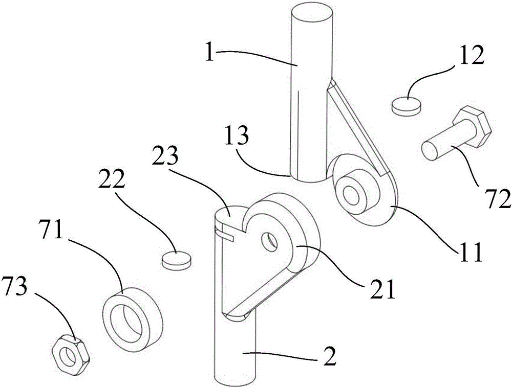
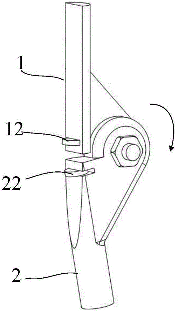
[0130] Such as figure 1 and figure 2 As shown, a resetting exoskeleton joint includes a first limb 1 and a second limb 2. In this example, the knee joint is taken as an example for illustration, wherein the first limb 1 corresponds to the upper joint, the second limb 2 corresponds to the lower joint, and the second limb 2 corresponds to the lower joint. The joint heads 11 and 21 of the first limb 1 and the second limb 2 are rotatably connected by bearings 71, bolts 72 and nuts 73. In order to make the first limb 1 and the second limb 2 reset quickly when they tend to stand upright, this example A resetting mechanism is arranged between the first limb 1 and the second limb 2 . In this example, a magnet attraction mechanism is used to reset, that is, a magnet 12 is set on the first limb 1, and an attraction element 22 that attracts the magnet 12 is arranged on the second limb 2 for suction. The attraction element 22 can be a steel column, iron column or magnet. The magnet 12...

Embodiment 2

[0132] Such as image 3 and Figure 4 As shown, in this example, the joint heads 11, 21 of the first limb 1 and the second limb 2 are rotationally connected by bearings 71, bolts 72, and nuts 73. In order to make the first limb 1 and the second limb 2 tend to stand upright, Can reset quickly, in this example, a resetting mechanism is provided between the first limb 1 and the second limb 2, which includes a spring 31 as a pressing mechanism, and a matching wedge 32 and wedge groove 33, and the spring 31 from The radial direction of the joint exerts elastic force on the wedge 32, wherein the spring 31 is vertically installed in the groove provided by the second limb 2, and the wedge groove 33 is opened on the arc-shaped outward expansion surface of the joint head 11 of the first limb 1, and the wedge 32 It is located above the spring 31 and is pressed tightly in the wedge groove 33. Through the inclined mating surface of the wedge groove 33 and the wedge block 32, the vertical ...

Embodiment 3

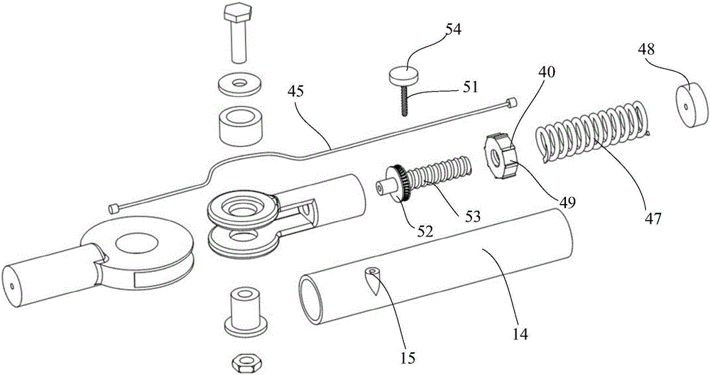
[0134] In this example, the reset is also carried out by using inclined plane fit. The difference from Example 2 is that the force application direction of the pressing mechanism is parallel to the axis of the joint. Such as Figure 5 to Figure 7 As shown, an inclined mating surface along the rotation direction is formed between the joint heads of the first limb 1 and the second limb 2, and the first limb 1 and the second limb 2 are compressed laterally by a tensioning or pressing mechanism , in the process of returning after bending, the force of the tensioning or pressing mechanism is applied to the inclined surface, so that the first limb 1 and the second limb 2 move to the initial position along the inclined surface.

[0135] In this example, a connection hole is provided at the center of the joint heads 11, 21 of the first limb 1 and the second limb 2, and a wedge plate 35 is set outside the second limb 2, and a boss 36 protrudes from the middle of the wedge plate 35 and ...


PUM


Abstract

The invention provides a reduction exoskeleton joint, which comprises a first limb and a second limb which are in rotary connection, and further comprises a reduction mechanism which is arranged between the first limb and the second limb, wherein the reduction mechanism is in charge of providing recovery force when the first limb and the second limb approach to an upright state so as to promote the joint to recover to the upright state, and the joint, under the circumstance of not being exerted with obvious torque, is kept under the upright state. The reduction mechanism can adopt magnetic attraction elements or wedge block-wedge groove structures and further comprises an elastic energy storage mechanism, and the reduction mechanism is capable of releasing elasticity so as to assist power in a process that the first limb and the second limb extend. The elastic energy storage mechanism is a torsional spring, a tension spring, a compression spring or a pneumatic push rod; and a limiting mechanism, which is used for limiting rotating angles of the first limb and the second limb, is arranged between the first limb and the second limb. The reduction exoskeleton joint disclosed by the invention is simple in structure; power assisting is achieved by virtue of a mechanical mode under the condition of not consuming external energy; and in addition, reduction from passive bending to active extending is achieved.

Description

technical field [0001] The invention belongs to the technical field of robot wearable equipment, and in particular relates to a reset exoskeleton joint and an exoskeleton booster device thereof. Background technique [0002] An exoskeleton robot is an active mechanical system that can be worn outside the human body and mechanically assisted by external energy or portable energy according to human motion posture or human brain ideas. In the military field, this kind of equipment can enable soldiers to carry more weapons and equipment, enhance the movement ability of soldiers, and effectively improve the combat capability of individual soldiers; in the civilian field, it can be widely used in mountaineering, tourism, firefighting, disaster relief, etc. In the medical field, exoskeleton robots can also be used to assist the disabled and the elderly to walk, and can also help patients who have temporarily lost their mobility to perform functional recovery training. Therefore, i...

Claims


Application Information

Patent Timeline
Patent Type & Authority Applications(China)
IPC IPC(8): A61H3/00
CPCA61H3/00A61H2003/005A61H2201/0165A61H2201/1635A61H2201/164A61H2201/1676A61H2203/0406
Inventor 袁博姜峰江敏李佳克孙梓瑜
Owner 重庆市牛迪科技发展有限公司
Why Eureka
Try Eureka