Vacuum die-casting machine

a die-casting machine and vacuum technology, applied in the field of vacuum die-casting machines, can solve problems such as gas inclusions in metal melts, and achieve the effect of influencing the pressure of the mold cavity

Active Publication Date: 2016-06-21
IDRA
View PDF6 Cites 5 Cited by
  • Summary
  • Abstract
  • Description
  • Claims
  • Application Information

AI Technical Summary

Benefits of technology

[0009]This arrangement has the advantage that the flow connection between the mold cavity and the warm holding oven does net have to be interrupted. It is therefore not necessary that the casting piston, which is movably disposed in the casting chamber needs to be moved into a position in which it blocks the flow path. Rather, the casting piston may advantageously remain in a retracted position in which the communication path between the mold cavity and the warm-holding oven is open. This also has the advantage that the casting piston is in a position as needed for the subsequent evacuation procedure for suctioning the metal melt into the casting chamber. The casting piston can remain in the retracted position during the closing of the movable mold half and during the subsequent evacuation procedure. Only after the metal melt has been transported into the casting chamber, the casting piston has to move the melt volume from the casting chamber into the mold cavity by a forward movement.
[0011]Basically, various operating arrangements may be used for setting the mold cavity pressure. In accordance with an advantageous embodiment, the operating arrangement can be formed by the movable mold half of the casting mold wherein, for the adjustment of the mold cavity pressure, the closing speed of the movable mold half is used. Normally, the movable mold half is moved during the closing procedure with a predetermined speed profile from which however it can be deviated for adjusting the mold cavity pressure. In particular, when the, mold halves, with the seal rope extending around the mold cavity at the front faces between the two mold halves, are engaged, an air volume is enclosed between the mold halves so that, upon further compressing of the movable mold half onto the stationary mold halt, an excess pressure can be, generated in the mold cavity. By reducing the engagement speed dynamically generated pressure peaks in the mold cavity can be avoided. In this way, the mold cavity pressure can be kept below the melt counter-pressure by controlling the closing speed of the movable mold half.
[0013]In accordance with another advantageous embodiment, a pressure valve is provided on the mold cavity via which the mold cavity is connected to the evacuation arrangement. The pressure valve is adjustable at least between an open position in which the mold cavity is in communication with the evacuation arrangement and a closed position. In a preferred embodiment, the pressure valve is in the form of a three-way valve which, in addition to the closed position and the open. position in which a communication path to the evacuation arrangement is provided, can be moved to a third position in which the mold cavity is placed into communication with the atmosphere. In this way, an additional setting can be provided in which the mold cavity pressure can be influenced. It is for example possible to keep the three-way valve in the evacuation posit ion or, respectively, to move it to this position when the mold cavity pressure is to be adjusted by the control arrangement. It is also possible as a result to move the three-way valve into a position which provides for communication with the atmosphere when the action for controlling the pressure of the mold cavity is to be adjusted.

Problems solved by technology

This may result in an excess pressure which may be transmitted from the mold cavity via the casting chamber to the metal melt in the warm-holding oven causing gas inclusions in the metal melt.

Method used


Image

  • Vacuum die-casting machine
  • Vacuum die-casting machine
  • Vacuum die-casting machine

Examples


Embodiment Construction

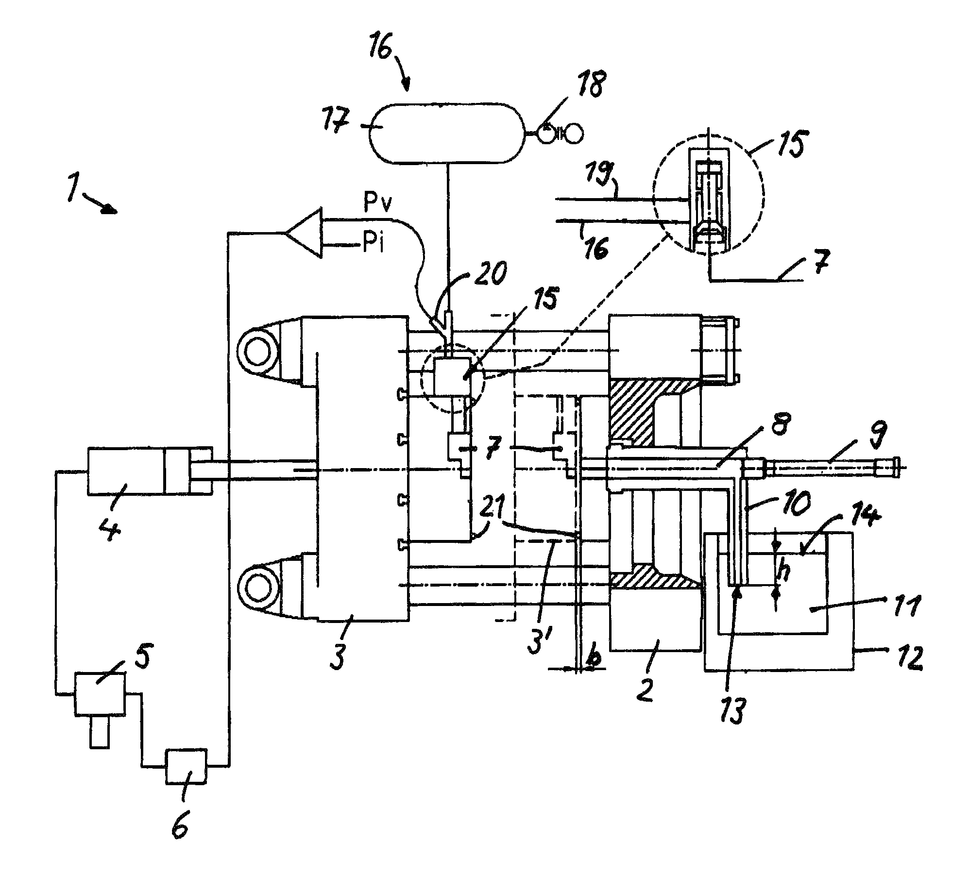
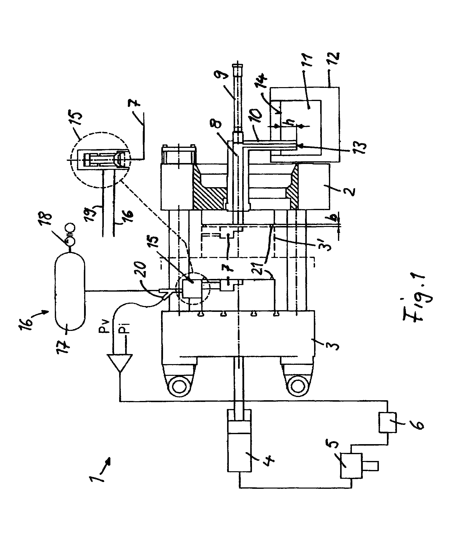
[0024]FIG. 1 shows a vacuum-die casting machine 1 which comprises two mold halves 2, 3 wherein the mold half 2 is stationary and the mold half 3 is movably supported. The mold half 3 is adjustable between a retracted position (3) as shown in solid lines and a position (3′) moved toward the stationary mold half and indicated by dashed lines. The movement of the mold half 3 is achieved by an actuator in the form of a hydraulic cylinder 4 to which hydraulic fluid is supplied via a hydraulic valve 5. The hydraulic valve 5 is controlled by control signals of a control arrangement 6.

[0025]Between the mold halves 2, 3, a casting or, respectively, molding cavity 7 for receiving a metal melt is enclosed. The mold cavity 7 is in flow communication with a casting chamber 8 in which a casting piston. 9 is movably supported. The casting chamber 8 is connected to a metal melt 11 disposed in a warm-holding oven 12 via a suction pipe 10. The suction pipe 10 extends so far into the metal melt 11 tha...


PUM

PropertyMeasurementUnit
mold cavity pressureaaaaaaaaaa
pressureaaaaaaaaaa
closing speedaaaaaaaaaa

Abstract

In a vacuum-die casting machine comprising a casting mold having stationary and movable mold halves defining therebetween a mold cavity, a casting chamber which is in communication with the mold cavity and includes a piston and an evacuation arrangement connectable to the casting chamber for drawing melt from a melt storage into the casting chamber, a control arrangement is provided for controlling the mold cavity pressure depending on the pressure difference between the mold cavity and a cavity pressure and a counter pressure of the metal melt.

Description

[0001]This is Continuation-in-Part application of pending international patent application PCT / EP2011 / 000376 filed Jan. 28, 2011.BACKGROUND OF THE INVENTION[0002]The invention resides in a vacuum die-casting machine which includes a mold with two mold halves forming therebetween a cavity which is in communication with a casting chamber to which molten metal is supplied from a holding oven.[0003]EP 0 790 090 discloses a vacuum die casting machine. which comprises a casting mold formed by two mold halves for receiving a metal melt. One of the mold halves is stationary and the second mold half is movable in the direction toward the stationary mold half. One of the mold halves is provided with a seal rope at the front edge thereof which extends between the mold halves so as to form a pressure-tight seal between the two mold halves. The casting cavity between the two mold halves is in communication with a casting chamber in which A casting piston is movably supported. The casting chamber...

Claims


Application Information

Patent Timeline
Patent Type & Authority Patents(United States)
IPC IPC(8): B22D17/14B22D17/04B22D18/08B22D17/32
CPCB22D18/08B22D17/14B22D17/32B22D17/04
Inventor BONI, ROBERTODIONI, FLORENZOHOEFER, WERNERGARY, RAINER
Owner IDRA
Why Eureka
Try Eureka