
Operating System For A Parking Brake

a technology of operating system and parking brake, which is applied in the direction of brake action initiation, braking system, axially engaging brake, etc., can solve the problems of far more complicated production, and achieve the effect of increasing the stability and life-time of the operating system

Inactive Publication Date: 2008-01-10
FICO CABLES
View PDF17 Cites 4 Cited by
  • Summary
  • Abstract
  • Description
  • Claims
  • Application Information

AI Technical Summary

Benefits of technology

[0014] Another advantage is that the connection between the operating element and the follower element is only interrupted, if the separating element is used. Accordingly, the hiding of the brake lever can be controlled by the driver and is therefore an optional feature and not inevitably performed each time the brake is applied.
[0015] The operating system comprises preferably a mounting plate to which the operating element and the follower element are rotatably attached. Preferably, a supporting element is additionally provided which is permanently connected to the operating element, wherein the operating element is attached to a first bearing of the mounting plate and the support element is attached to a second bearing of the mounting plate. This double bearing significantly increases the stability and life-time of the operating system.
[0018] All three functions of the operating system, i.e. the operation of the brake by pulling the lever, the disengaging of the brake with the first control element and the lowering of the lever with the second control element can therefore be easily performed with a single hand. The first as well as the second control element are each preferably provided as an operating knob. In an alternative, presently most preferred embodiment, the second control element for operating the separating element is provided as a turning handle.
[0025] The second aspect of the present invention is particularly useful, if the control element for a release of the parking brake can be operated independently from the position of the brake lever. If the brake lever is no longer involved in the release of the brake, the supervising system preferably assures that the sudden release of the parking brake will not lead to unsafe conditions of the vehicle.

Problems solved by technology

As a result it is for example possible to disengage the parking brake simply by pressing an operating knob similar to an electrical parking brake, which is by far more complicated to produce.

Method used


Image

  • Operating System For A Parking Brake
  • Operating System For A Parking Brake
  • Operating System For A Parking Brake

Examples


Embodiment Construction

[0039] In the following several presently preferred embodiments of the present invention are described with reference to a manual parking brake for a motor vehicle. However, it is to be understood that the present invention may also be used in other technical fields where a brake is manually operated.

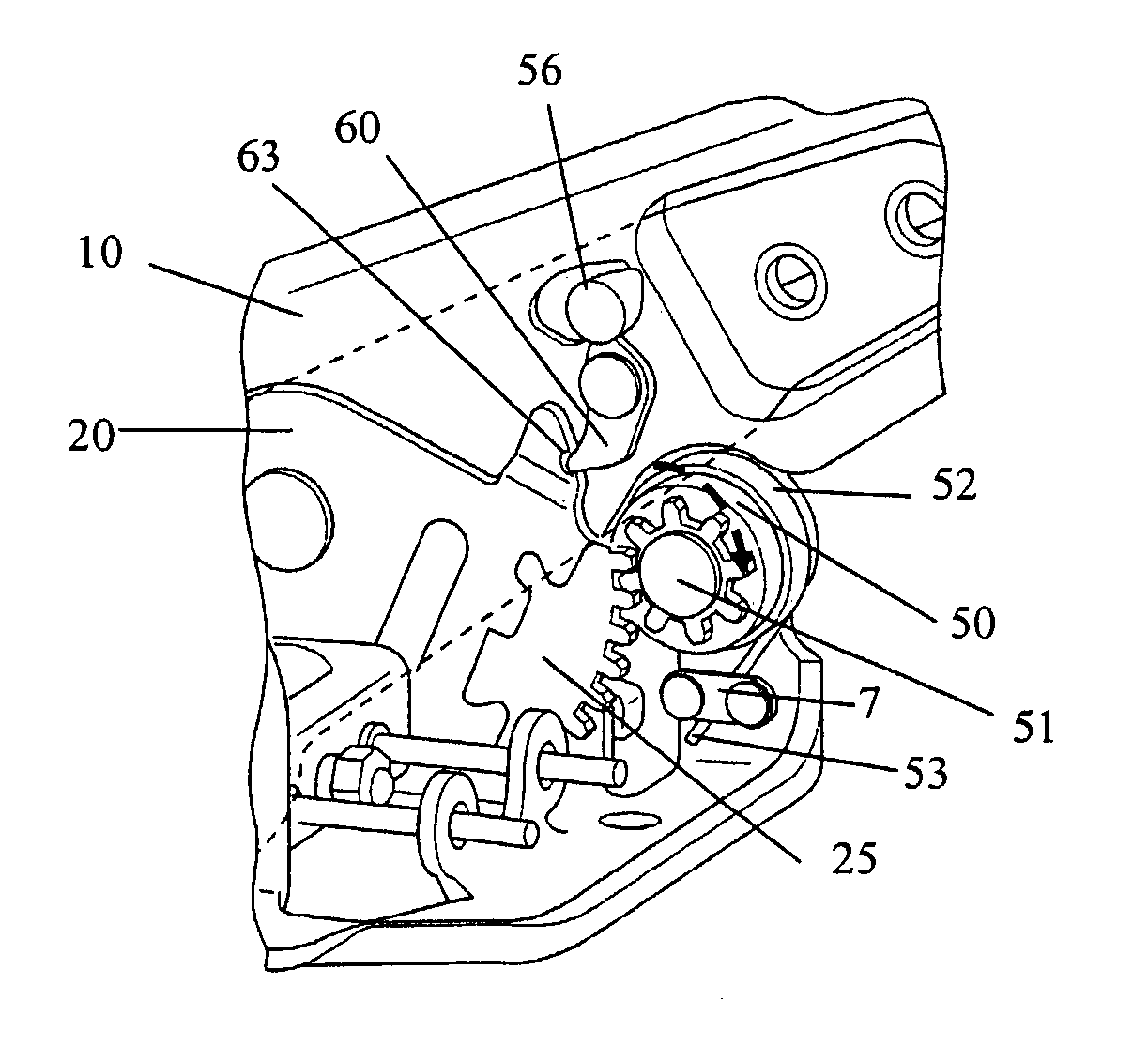
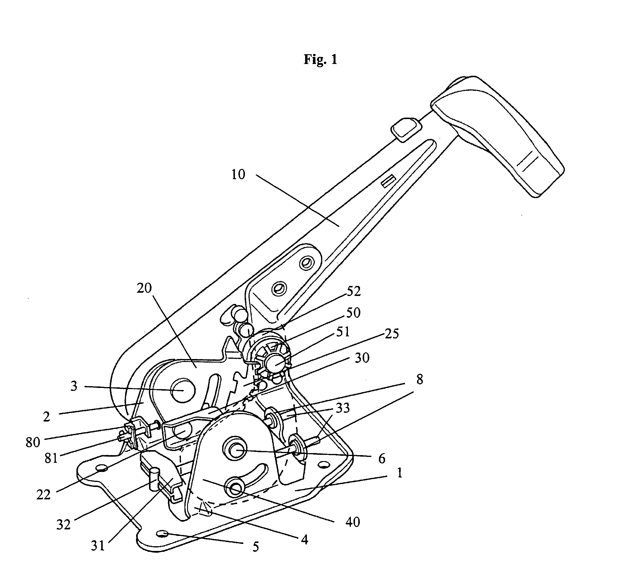
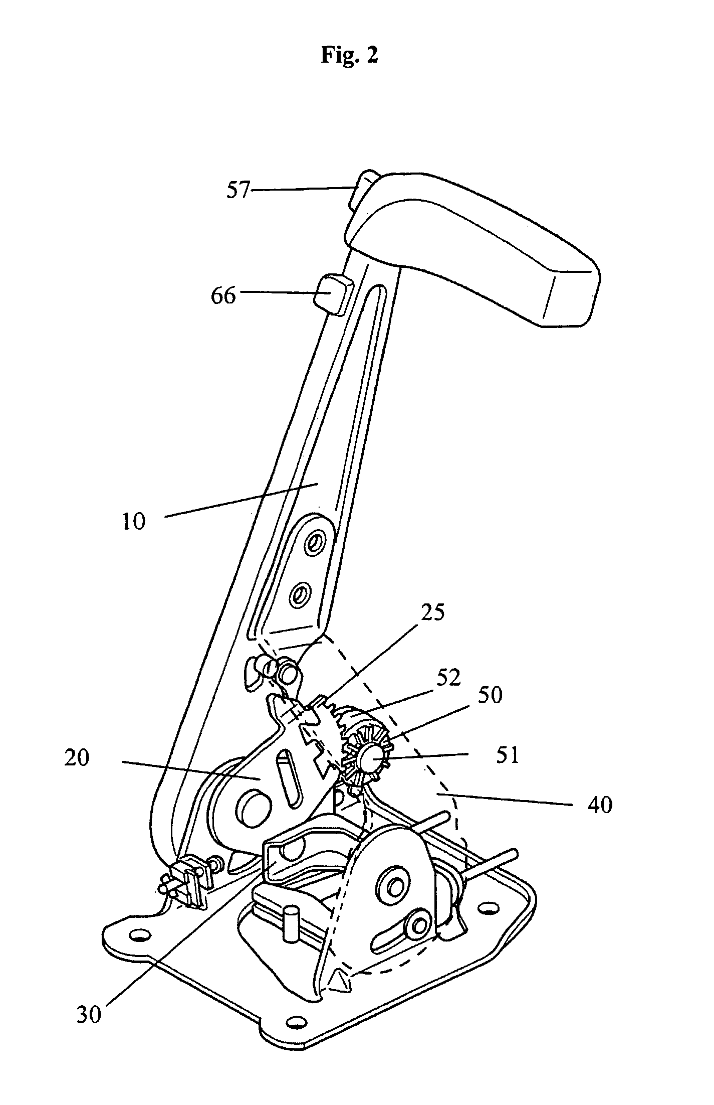
[0040]FIG. 1 shows a perspective general view of a first embodiment. A brake lever 10, being preferably made in one piece, is rotatably arranged on an upright mounting projection 2 of a mounting plate 1. The brake lever 10 can be rotated from a lower position to an upper position which is shown in FIG. 2. The mounting plate 1 comprises holes 5 or the like in order to attach the overall system to a motor vehicle.

[0041] A pulling lever 20 is rotatably arranged preferably on the same axle 3 around which the brake lever 10 is rotated. On the side of the pulling lever 20 directed to the brake lever 10 the pulling lever 20 comprises a projection 21 which extends through an elongated hole 11...


PUM


Abstract

An operating system for a parking brake, in particular of a motor vehicle, includes an operating element which is manually brought from a release position to a brake position for engaging the parking brake and which can be removed from the brake position without disengaging the parking brake. The operating system includes a follower element which is connected to the operating element such that the follower element follows any movement of the operating element. Further, the operating system includes a releasable locking mechanism with a locking element to lock the follower element in the brake position and a separating element which allows to separate the connection between the operating element and the follower element independently from the releasable locking mechanism.

Description

THE TECHNICAL FIELD [0001] The present invention relates to an operating system for a manually operated parking brake, in particular of a motor vehicle. THE PRIOR ART [0002] Typically, parking brakes of a vehicle are manually operated by a lever which is moved from a lower position to an upper position. The lever is generally arranged between the seats of the driver and the front-seat passenger. A ratchet mechanism avoids that the parking brake disengages by itself. In the applied position the lever remains in its upper position. For a release of the brake, the braking lever typically comprises an operating knob at its upper end which serves to release the ratchet mechanism. [0003] However, for a flexible use of the passenger compartment it is a disadvantage if the lever remains in the upper position, since it blocks for example a rotation of the seats of the driver and the front seat passenger in a camping car. Also for aesthetic reasons it as advantageous if the brake lever can be...

Claims


Application Information

Patent Timeline
Patent Type & Authority Applications(United States)
IPC IPC(8): F16D65/14F16D66/00B60T7/10
CPCB60T7/105
Inventor PRAT TERRADES, JAUMEJORNET, JORDI V.
Owner FICO CABLES
Learn More