Removable corner guard for control tables or tool boxes

a technology for tool boxes and control tables, applied in the field of corner guards, can solve the problems of not providing a corner guard, the patents fail to describe the corner guard for the control table or the tool box, etc., and achieve the effect of convenient transportation

Inactive Publication Date: 2016-06-28
WILLIAM FRICK
View PDF37 Cites 1 Cited by
  • Summary
  • Abstract
  • Description
  • Claims
  • Application Information

AI Technical Summary

Benefits of technology

[0007]A removable corner guard is provided. The removable corner guard is especially suitable for protecting the corners of, for example, control tables or tool boxes from deformations and from scratches. Further, the corner guard may be used as decorative addition to an otherwise plain control table or tool box. The device has a semi-rigid rubber housing which covers securing anchors having an internal skeleton. An extended ridge on a lower end of the corner guard locks the corner guard at the lower end of the edge of the control table. The corner guard may be adjusted to fit control tables or tool boxes of various sizes. The extended ridge of the lower end may first be secured to the lower end of the control table or tool box and then the top end of the corner guard may rest on the top end of the control table or tool box by a tab. A non-slip textured exterior surface may allow for the device to be easily transported.
[0008]An advantage of the present corner guard is that the present corner guard may have various durometer measurements so as to provide a guard of various stiffness levels.

Problems solved by technology

However, these patents fail to describe a corner guard for a control table or tool box which is easy to use and efficient as is described in the present application.
Further, these patents fail to provide a corner guard which has an internal skeleton for securing an anchor to a control table.

Method used


Image

  • Removable corner guard for control tables or tool boxes
  • Removable corner guard for control tables or tool boxes
  • Removable corner guard for control tables or tool boxes

Examples


Embodiment Construction

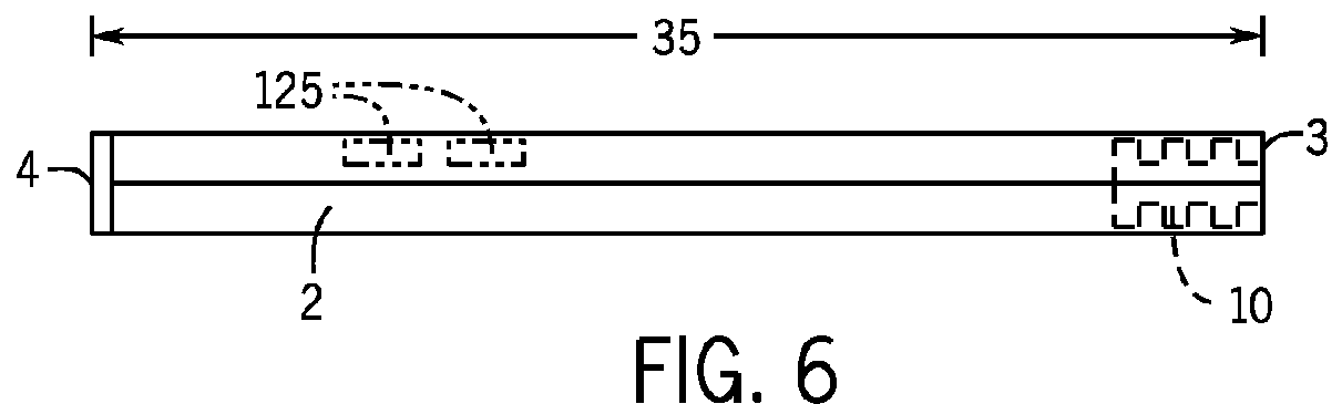
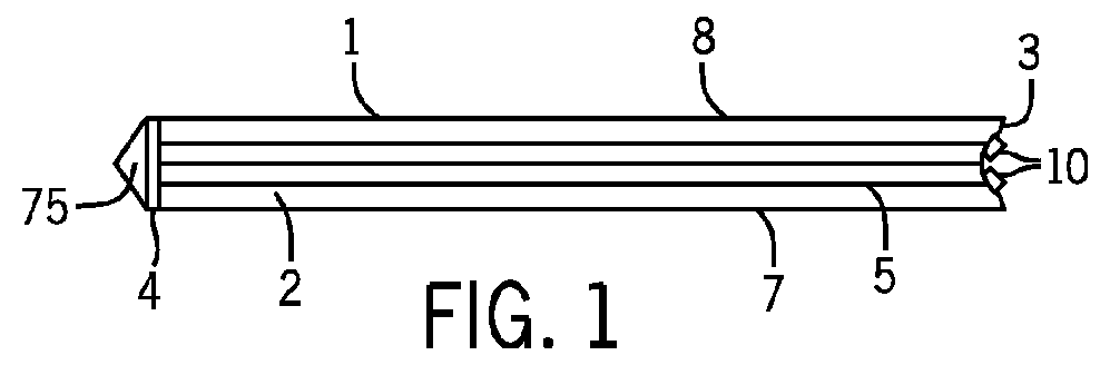
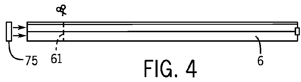
[0033]A removable corner guard is provided. The removable corner guard is especially suitable for protecting the corners of, for example, control tables or tool boxes from deformations and from scratches. Further, the corner guard may be used as decorative addition to an otherwise plain control table or tool box. The device has a semi-rigid rubber housing which covers securing anchors having an internal skeleton. An extended ridge on a lower end of the corner guard locks the corner guard at the lower end of the edge of the control table. The corner guard may be adjusted to fit control tables or tool boxes of various sizes. The extended ridge of the lower end may first be secured to the lower end of the control table or tool box and then the top end of the corner guard may rest on the top end of the control table or tool box by a tab. A non-slip textured exterior surface may allow for the device to be easily transported.

[0034]Referring now to the drawings, a corner guard 1 for a cont...


PUM


Abstract

A removable corner guard is provided. The removable corner guard is especially suitable for protecting the corners of, for example, control tables or tool boxes from deformations and from scratches. Further, the corner guard may be used as decorative addition to an otherwise plain control table or tool box. The device has a semi-rigid rubber housing which covers securing anchors having an internal skeleton. An extended ridge on a lower end of the corner guard locks the corner guard at the lower end of the edge of the control table. The corner guard may be adjusted to fit control tables or tool boxes of various sizes. A non-slip textured exterior surface may allow for the device to be easily transported.

Description

CROSS REFERENCE TO RELATED APPLICATIONS[0001]The following application is based on and claims the priority benefit of U.S. provisional application Ser. No. 61 / 879,734 filed Sep. 19, 2013; the entire contents of which are incorporated by reference.BACKGROUND OF THE INVENTION[0002]A removable corner guard is provided. The removable corner guard is especially suitable for protecting the corners of, for example, control tables or tool boxes from deformations and from scratches. Further, the corner guard may be used as decorative addition to an otherwise plain control table or tool box. The device has a semi-rigid rubber housing which covers securing anchors having an internal skeleton. An extended ridge on a lower end of the corner guard locks the corner guard at the lower end of the edge of the control table. The corner guard may be adjusted to fit control tables or tool boxes of various sizes. The extended ridge of the lower end may first be secured to the lower end of the control tab...

Claims


Application Information

Patent Timeline
Patent Type & Authority Patents(United States)
IPC IPC(8): A47B95/04B25H3/02A47B13/08A47B96/00
CPCA47B95/043A47B13/08A47B96/00B25H3/02
Inventor BRANDT, JEFFREY H.SVASTISALEE, CHAD E.PRAKASH, SURAJ
Owner WILLIAM FRICK
Why Eureka
Try Eureka