Device for dispensing a dental material and method of dispensing

a technology for dental materials and devices, applied in dental surgery, liquid transfer devices, tooth capping, etc., to achieve the effect of facilitating device activation, reducing the yield or elasticity of the second compartment, and facilitating the expansion of the second compartmen

Active Publication Date: 2016-06-28
3M INNOVATIVE PROPERTIES CO
View PDF43 Cites 3 Cited by
  • Summary
  • Abstract
  • Description
  • Claims
  • Application Information

AI Technical Summary

Benefits of technology

[0018]The invention may be advantageous for providing two- or multi-component materials in single-use quantities. The invention may further allow for rapidly providing an amount of two-component material in a single activation step. Accordingly the device of the invention may help minimizing the number of handling steps to be taken to activate the device and thus may be convenient to use. This may further help minimizing the time needed to prepare a dental material. Further, with the invention a device may be provided which allows storage of the material over a relatively long time. The invention further may provide for a device that is relatively inexpensive.
[0048]In one embodiment the method further comprises the step of compressing the first compartment on a generally flat surface by use of a thumb or finger, and the step of rolling the thumb or finger towards the second compartment to compress the second compartment. Thus the device may be relative easy to use. Further the device may not be bent after compressing the first compartment as it may be practiced with other devices according to the background art to prevent the first and / or second components from flowing back toward the first component. The method may further comprise the steps of removing an applicator (for example a brush) from the channel, and agitating the components received in the reservoir by use of an applicator. The method may further comprise the step of rewetting the applicator by pushing the applicator through one of the layers into the reservoir. Thereby the layer may have an opening through which the applicator can be pushed, or the layer may be closed so that the layer opens as a consequence of pushing the applicator through the layer. The layer may have a predetermined weakened area for pushing the applicator through.

Problems solved by technology

However in the alternative the second compartment may be generally incompressible or may be compressible at relatively high forces only.

Method used


Image

  • Device for dispensing a dental material and method of dispensing
  • Device for dispensing a dental material and method of dispensing

Examples


Embodiment Construction

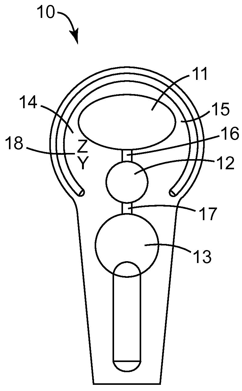
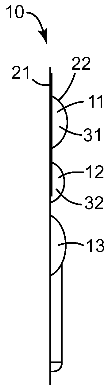
[0050]FIG. 1A shows a top view and FIG. 1B shows a cross-sectional side view of a device 10. The device 10 has a first compartment 11, a second compartment 12 and a reservoir 13.

[0051]The compartments 11, 12 are formed between a bottom layer 21 and a top layer 22. The layers 21, 22 are interconnected with each other to encapsulate a first component 31 within the first compartment 11 and a second component 32 in the second compartment 12. In particular the layers 21, 22 in the example are interconnected in a major interconnection area 14 around other areas in which an interconnection is suspended. For example the first compartment 11 and the second compartment 12 each are formed between non-interconnected areas of the layers 21, 22 and the interconnection area 14 entirely surrounds and thus seals such non-interconnected areas. Further the interconnection area 14 comprises a permanent interconnection area 15 and first non-permanent interconnection area 16 and second non-permanent inte...


PUM

PropertyMeasurementUnit
thicknessaaaaaaaaaa
thicknessaaaaaaaaaa
thicknessaaaaaaaaaa

Abstract

A device for dispensing a dental material comprises first compartment and the second compartment formed between interconnected sheet-like layers. The compartments encapsulate a first flowable component and a second flowable component of the dental material. The device has a first seal and a second seal for sealing the first compartment and the second compartment in the device. Each seal is adapted to automatically open in consequence of forcing a component of the dental material toward the seal. The capacity of the first compartment and the second compartment relative to each other is dimensioned such that squeezing out the first component from the first compartment by compressing the first compartment causes the first seal and the second seal to open. The device preferably allows easy and quick activation for use of the stored components.

Description

CROSS REFERENCE TO RELATED APPLICATIONS[0001]This application is a national stage filing under 35 U.S.C. 371 of PCT / US2012 / 064276, filed Nov. 9, 2012, which claims priority to European Application No. 11188772.5, filed Nov. 11, 2011, the disclosures of which are incorporated by reference in their entirety herein.FIELD OF THE INVENTION[0002]The invention relates to a device for dispensing a dental material, and in particular to a device for dispensing multi-component dental material. The invention further relates to a method of dispensing a dental material from such a device.BACKGROUND ART[0003]A variety of dental compositions are provided in the form of two or more flowable components that are separately stored, and mixed together only shortly before use. There are different packages for separately storing components of such multi-component compositions. Examples of commonly-used packages for multi-component compositions include dual-chamber cartridges, dual-chamber syringes or dual...

Claims


Application Information

Patent Timeline
Patent Type & Authority Patents(United States)
IPC IPC(8): B67D7/78B65D75/32A61C5/06B65D81/32A61C5/64
CPCA61C5/068A61C5/064A61C5/066B65D75/324B65D75/328B65D81/3266A61C5/64
Inventor PEUKER, MARCWALTER, ALEXANDERPOSCHMANN, DIETER
Owner 3M INNOVATIVE PROPERTIES CO
Why Eureka
Try Eureka