Cutting tool mounting assembly

a technology for mounting parts and cutting tools, applied in the direction of cutting machines, earthwork drilling and mining, etc., can solve the problems of wear and/or failure of one or more cutting tool assembly components, wear and/or failure, and one source of wear, so as to facilitate friction and reduce vibration

Inactive Publication Date: 2016-07-05
KENNAMETAL INC
View PDF23 Cites 3 Cited by
  • Summary
  • Abstract
  • Description
  • Claims
  • Application Information

AI Technical Summary

Benefits of technology

[0010]In accordance with an aspect of the invention, a cutting tool mounting assembly adapted for attachment to a surface of a rotatable driving member of a cutting tool machine, the cutting tool mounting assembly including: a tool holder having a key shank; a base attached to the surface of the rotatable driving member, the base having a mounting groove for receiving the key shank of the tool holder; a resilient retention structure configured to interact with the base and the tool holder to facilitate a friction fit between the tool holder and the base; and wherein tool holder includes a retention post configured for cooperating with the base for connecting the tool holder to the base. Another aspect includes a dampening element configured between the tool holder and the base for reducing vibration therebetween.

Problems solved by technology

The cutting bit or tool, the tool holder and the base are each subjected to considerable stresses during mining operations, road milling operations or other like operations that can lead to wear and / or failure of one or more of the cutting tool assembly components.
One source of wear occurs as a result of the mounting between the tool holder and the base.
Nonetheless, due to operation of such cutting tool assemblies in severe operating conditions wear and / or failure will occur.
This type of damage can make it very difficult to disassemble the cutting tool assembly components and replace the components that are damaged.
Thus, it can be appreciated that cutting tool assemblies can experience wear and / or failure in a number of ways due to the environment in which they operate and must be frequently replaced.

Method used


Image

  • Cutting tool mounting assembly
  • Cutting tool mounting assembly
  • Cutting tool mounting assembly

Examples


Embodiment Construction

[0021]The following description is for purposes of illustrating various aspects of the invention only and not for purposes of limiting the scope of the invention.

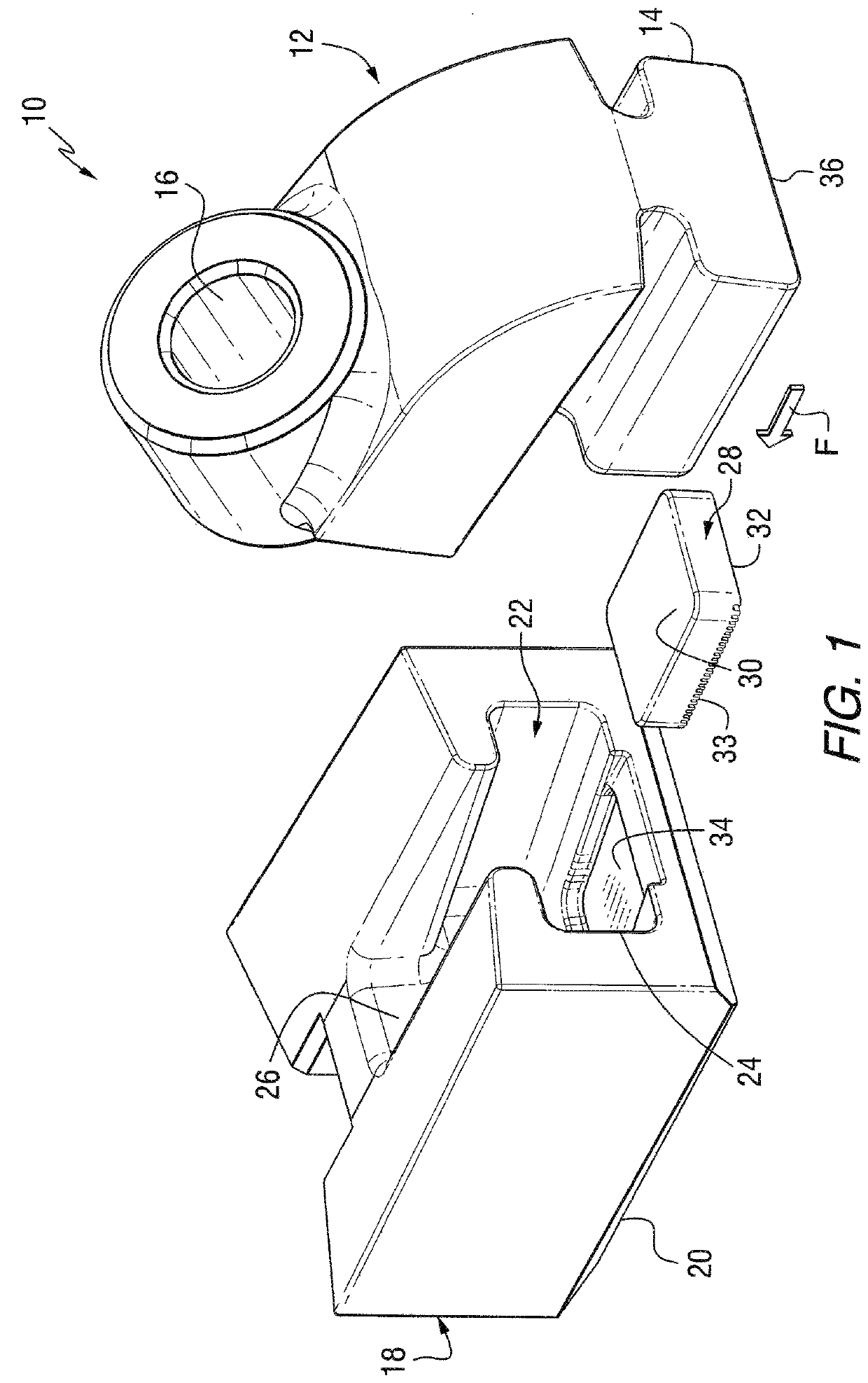
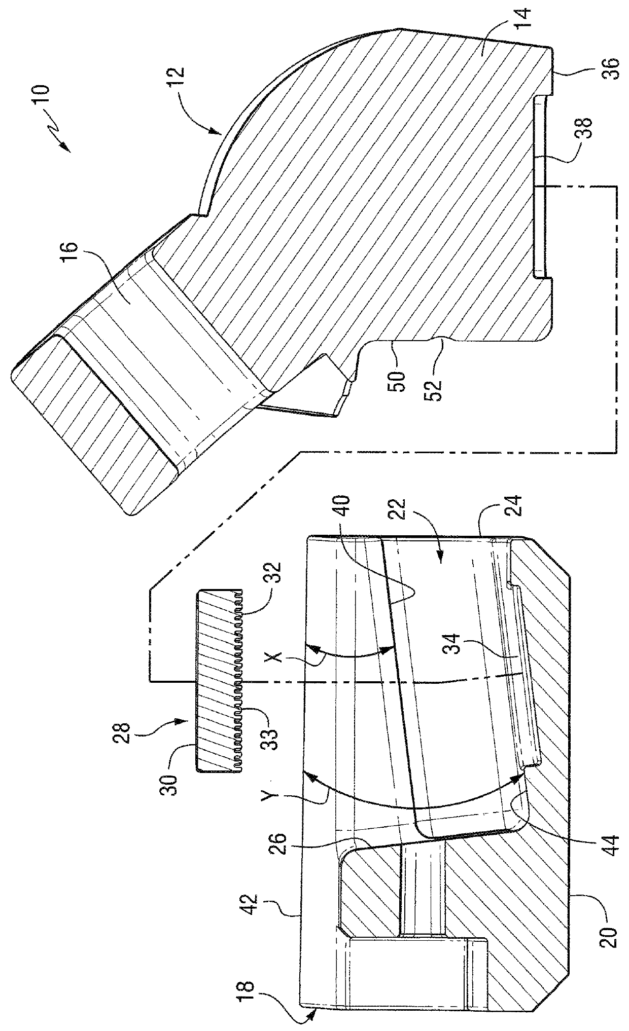
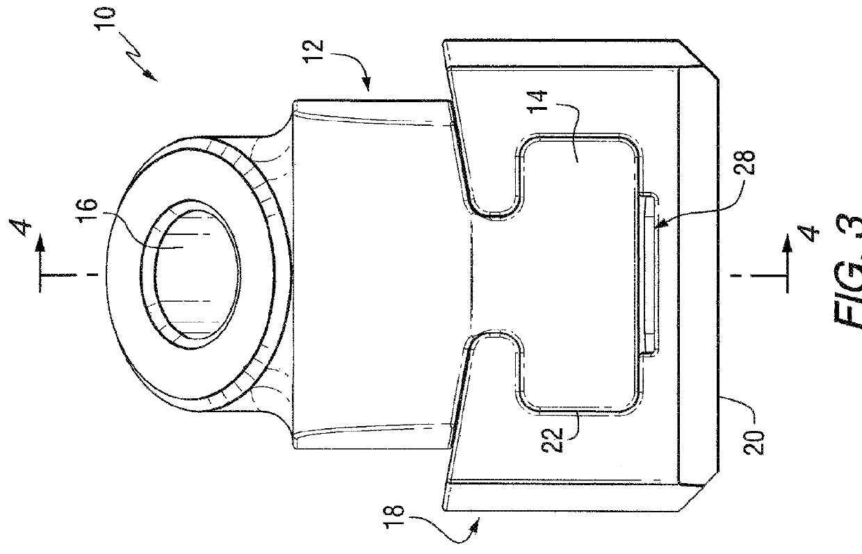
[0022]Referring to the Figures, there is illustrated a cutting tool mounting assembly, generally designated as reference number 10, in accordance with various aspects of the invention. It will be appreciated that the invention has application to various kinds of cutting tools useful in various kinds of cutting operations. Exemplary operations include, without limitation, road planing (or milling), coal mining, concrete cutting, and other kinds of cutting operations wherein a cutting tool with a hard cutting member impinges against a substrate (e.g., earth strata, pavement, asphaltic highway material, concrete, and the like) breaking the substrate into pieces of a variety of sizes including larger-size pieces or chunks and smaller-sized pieces including dust-like particles. In addition, it will be appreciated that the cuttin...


PUM


Abstract

A cutting tool mounting assembly adapted for attachment to a surface of a rotatable driving member of a cutting tool machine, includes: a tool holder having a key shank; a base attached to the surface of the rotatable driving member, the base having a mounting groove for receiving the key shank of the tool holder; a resilient retention structure configured to interact with the base and the tool holder to facilitate a friction fit between the tool holder and the base; and wherein tool holder includes a retention post configured for cooperating with the base for connecting the tool holder to the base. Also included is a dampening element configured between the tool holder and the base for reducing vibration therebetween.

Description

CROSS REFERENCE TO RELATED APPLICATION[0001]This application claims the benefit of U.S. patent application Ser. No. 13 / 711,981, filed Dec. 12, 2012, the entire content of which is hereby incorporated by reference.BACKGROUND OF THE INVENTION[0002]The invention pertains generally to a cutting tool mounting assembly that is useful in association with machines for impinging a substrate or earth strata such as, for example, asphaltic roadway material, coal deposits, mineral formations and the like. More particularly, the invention pertains to a cutting tool mounting assembly, as well as the individual components of the assembly.[0003]One typically uses such an assembly in conjunction with a rotatable drum or driven member. The driven member rotates in such a fashion to drive the rotatable cutting bit or tool into earth strata to disintegrate the same into smaller pieces including fine particulates, i.e., cutting debris. The cutting bit or tool, the tool holder and the base are each subje...

Claims


Application Information

Patent Timeline
Patent Type & Authority Patents(United States)
IPC IPC(8): E21C35/19
CPCE21C35/19
Inventor BOOKHAMER, PAUL A.PAROS, NICHOLAS J.WEBER, LUKE A.
Owner KENNAMETAL INC
Why Eureka
Try Eureka