Piezoelectric microactuator with restraining layer for control of bending

a technology of bending control and micro-actuation, applied in the field of suspension, can solve problems such as stroke length loss

Active Publication Date: 2016-07-12
MAGNECOMP
View PDF58 Cites 15 Cited by
  • Summary
  • Abstract
  • Description
  • Claims
  • Application Information

AI Technical Summary

Benefits of technology

[0014]The inventors of the application have identified a source of lost PZT stroke length in a suspension having a PZT microactuator mounted thereto according to the prior art, and have developed a PZT microactuator structure and method of producing it that eliminates the source of that lost stroke length.
[0020]The present invention is of a PZT element that has one or more stiff restraining layers or restraining elements bonded onto at least one side or face opposite the side or face on which the PZT is mounted to the suspension, in order to reduce, eliminate, change the direction of, or otherwise control bending of the PZT when it is actuated. The counterintuitive result is that even though the PZT has an stiff layer added to it that, at least nominally, restrains the expansion and contraction of the PZT, the effective linear stroke distance achieved actually increases. A PZT having a restraining layer according to the invention can be used as a microactuator in a hard disk drive suspension, although it could be used in other applications as well.
[0021]In a preferred embodiment the effect of the restraining layer is to actually change the direction of bending. Thus, for a PZT that is bonded on its bottom surface to the suspension, the presence of the restraining layer has the effect that when the piezoelectric element is actuated by a voltage that causes the piezoelectric element to expand, the piezoelectric element bends in a direction that causes the top face to become net concave in shape; and when the piezoelectric element is actuated by a voltage that causes the piezoelectric element to contract, the piezoelectric element bends in a direction that causes the top face to become net convex in shape. The effect is therefore to actually increase the effective linear expansion in expansion mode, and to increase the effective linear contraction in contraction mode. The presence of the restraining layer therefore actually increases the effective stroke length.
[0023]The constraining layer may be larger (of greater surface area) than the PZT element, the same size as the PZT element, or may be smaller (of lesser surface area) than the PZT element. In a preferred embodiment, the constraining layer is smaller than the PZT element, giving the microactuator a step-like structure with the shelf of the step uncovered by the restraining layer, and with the shelf being where the electrical connection is made to the PZT element. One benefit of such a construction including a shelf where the electrical connection is made is that the completed assembly including the electrical connection has a lower profile than if the restraining layer covers the entire PZT. A lower profile is advantageous because it means that more hard drive platters and their suspensions can be stacked together within a given platter stack height, thus increasing the data storage capacity within a given volume of disk drive assembly.
[0024]Simulations have shown that microactuators constructed according to the invention exhibit enhanced stroke sensitivity, and also exhibited reduced sway mode gain and torsion mode gain. These are advantageous in increasing head positioning control loop bandwidth, which translates into both lower data seek times and lower susceptibility to vibrations.
[0025]An additional advantage of adding a constraining layer(s) or element(s) to the PZT according to the invention is that in hard disk drives today, the suspension and its components including the PZT are usually very thin. Microactuators used in today's DSA suspension designs in which the PZTs are mounted at the mount plate, are on the order of 150 μm thick. In gimbal-mounted DSA suspension designs the PZTs are even thinner, often being less than 100 μm thick. The PZT material is therefore very thin and brittle, and can crack easily during both manufacturing / assembly, including both the process of manufacturing the PZT microactuator motor itself as well as the automated pick-and-place operation in the suspension assembly process. It is expected that PZTs in future generation hard drives will be 75 μm thick or thinner, which will exacerbate the problem. It is anticipated that PZTs this thin will not only be susceptible to damage during manufacturing / assembly, but could also be vulnerable to cracking or breaking when the disk drive experiences shock, i.e., g-forces. The additional stiff, resilient constraining layer according to the present invention provides additional strength and resiliency to the PZT thus helping to prevent the PZT from cracking or otherwise mechanically failing during manufacturing / assembly and during shock events.

Problems solved by technology

Thus, although purely linear expansion and contraction of the PZT upon actuation is desired, in the conventional mounting the PZT experiences bending either up or down which results in lost stroke length.

Method used


Image

  • Piezoelectric microactuator with restraining layer for control of bending
  • Piezoelectric microactuator with restraining layer for control of bending
  • Piezoelectric microactuator with restraining layer for control of bending

Examples


Embodiment Construction

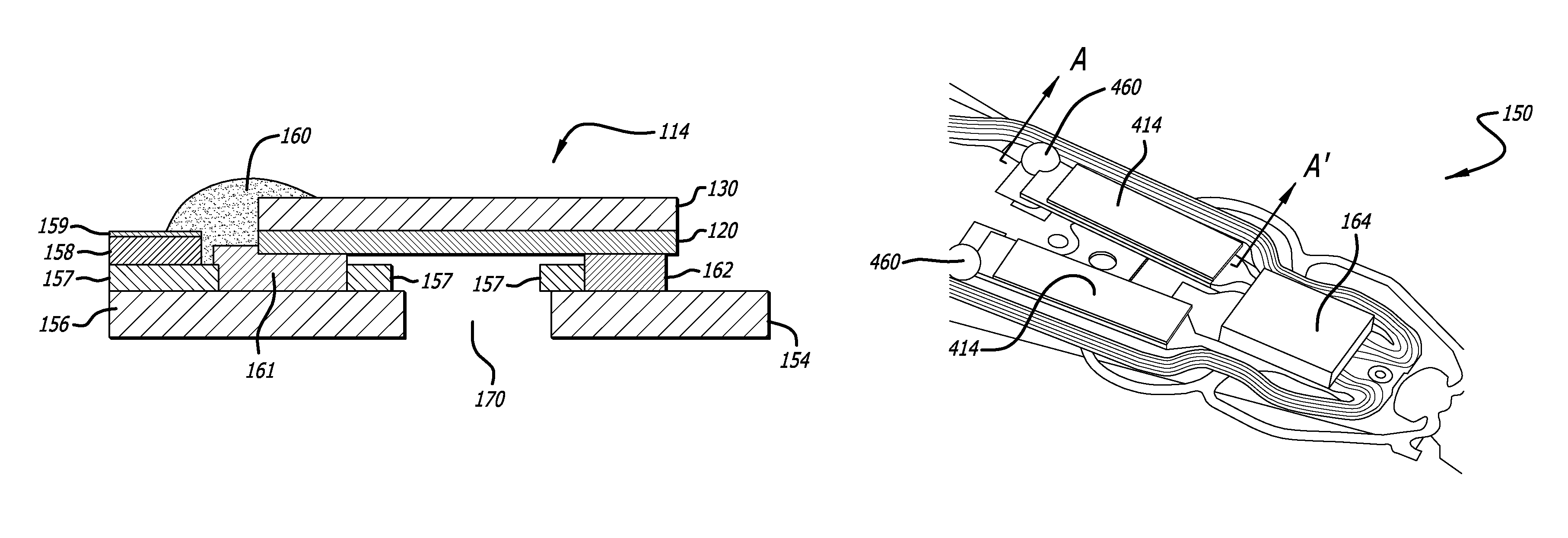
[0059]FIG. 7 is a side sectional view of a PZT microactuator assembly 114 having a constraining layer 130 bonded thereto in accordance with an embodiment of present invention. In keeping with the orientation shown in the figure, the side of the PZT which is bonded to the suspension will be referred to as the bottom side 129 of PZT 114, and the side of the PZT away from the side at which the PZT is bonded to the suspension will be referred to as the top side 127. According to the invention, one or more constraining layers or constraining elements 130 is bonded to the top side 127 of microactuator PZT element 120. The constraining layer 130 preferably comprises a stiff and resilient material such as stainless steel and is preferably bonded directly to the top surface 127 of the PZT element 120 including its top electrode 126, or the SST material may itself serve as the top electrode thus making it unnecessary to separately metalize the top surface. The constraining layer 130 is stiff ...


PUM

PropertyMeasurementUnit
Young's modulusaaaaaaaaaa

Abstract

A PZT microactuator such as for use in a hard disk drive has a restraining layer bonded on its side that is opposite the side on which the PZT will be mounted. The restraining layer comprises a stiff and resilient material such as stainless steel. The restraining layer can cover all of the top of the PZT, or most of the top of the PZT with an electrical connection being made to the PZT where it is not covered by the restraining layer. The restraining layer reduces bending of the PZT as mounted and hence increases effective stroke length, or reverses the sign of the bending which increases the effective stroke length of the PZT even further.

Description

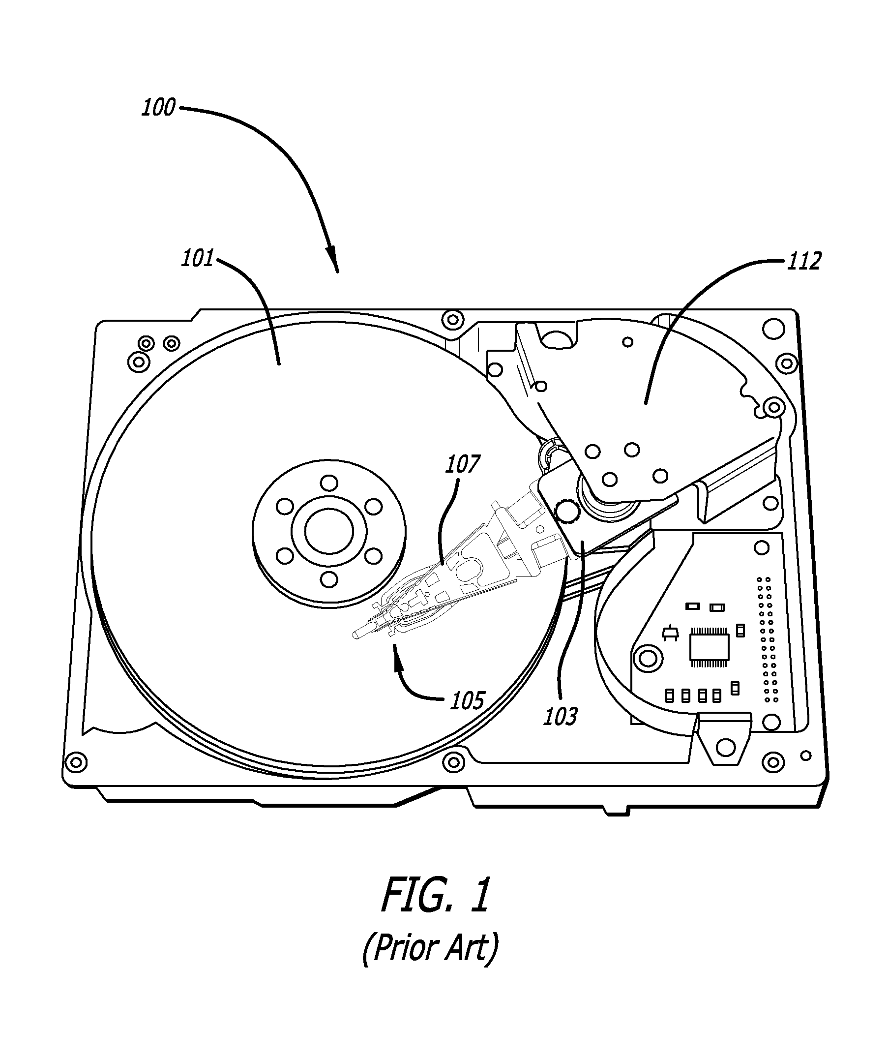
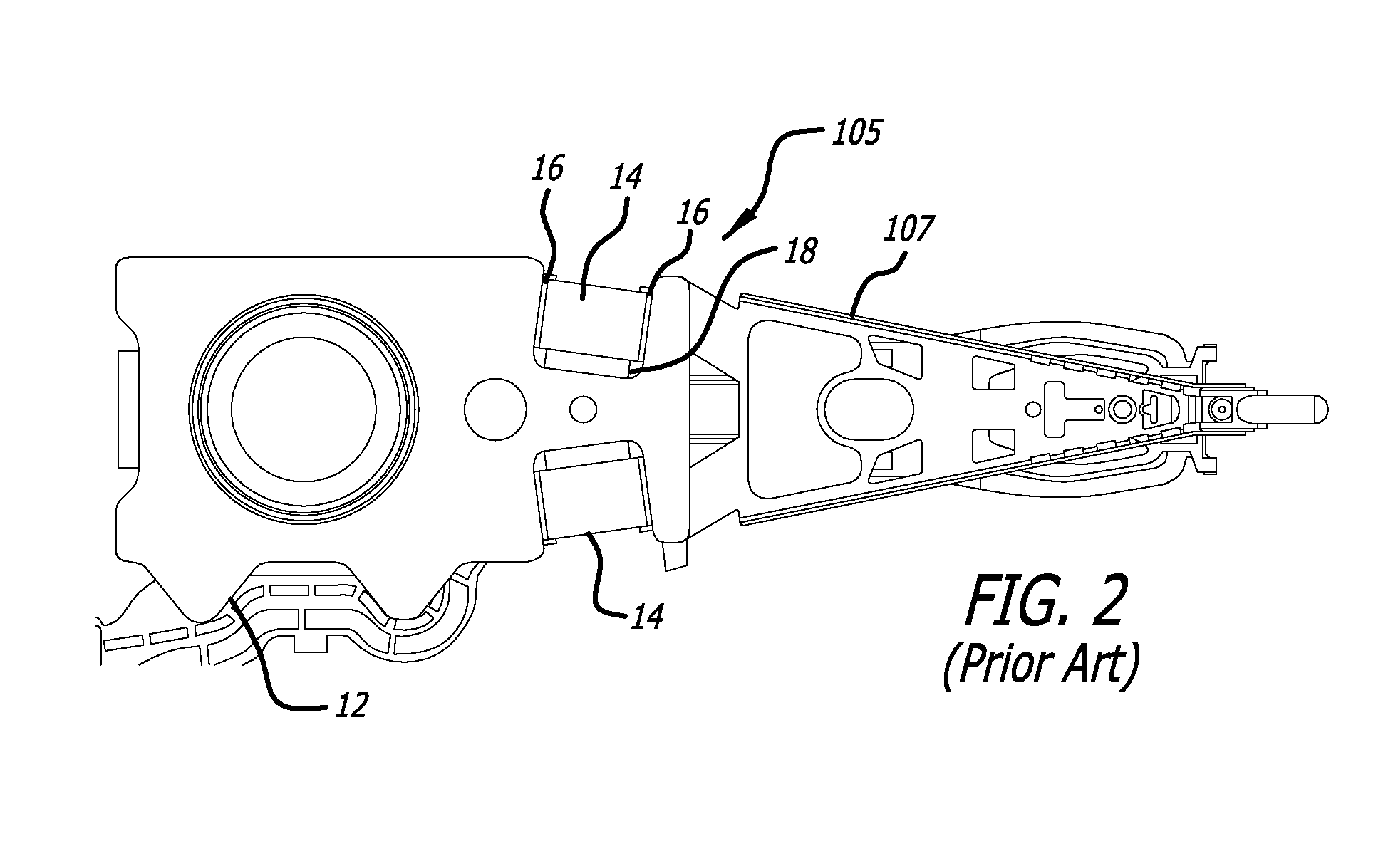
CROSS-REFERENCE TO RELATED APPLICATIONS[0001]This application claims priority from provisional patent application Nos. 61 / 802,972 filed Mar. 18, 2013, and 61 / 877,957 filed Sep. 14, 2013, the disclosures of which are hereby incorporated by reference in their entireties.BACKGROUND OF THE INVENTION[0002]1. Field of the Invention[0003]This invention relates to the field of suspensions for hard disk drives. More particularly, this invention relates to the field of a piezoelectric microactuator for a disk drive suspension, the microactuator having a restraining layer bonded thereto to reduce or control bending of the microactuator upon actuation.[0004]2. Description of Related Art[0005]Magnetic hard disk drives and other types of spinning media drives such as optical disk drives are well known. FIG. 1 is an oblique view of an exemplary prior art hard disk drive and suspension for which the present invention is applicable. The prior art disk drive unit 100 includes a spinning magnetic disk...

Claims


Application Information

Patent Timeline
Patent Type & Authority Patents(United States)
IPC IPC(8): G11B5/48
CPCG11B5/4873G11B5/4846G11B5/4806G11B5/483G11B5/48G11B5/5552H02N2/02H10N30/206
Inventor ZHANG, LONGHAHN, PETEREE, KUEN CHEE
Owner MAGNECOMP
Why Eureka
Try Eureka