Switch mechanism and electronic device

a technology of electronic devices and switches, applied in the direction of electric switches, contact operating parts, electrical equipment, etc., can solve the problems of unintended wrong operation, unsatisfactory detection degree of operation,

Active Publication Date: 2016-07-12
RICOH KK
View PDF10 Cites 0 Cited by
  • Summary
  • Abstract
  • Description
  • Claims
  • Application Information

AI Technical Summary

Benefits of technology

[0010]According to another aspect of the present invention, there is provided an electronic device including a switch mechanism and a processing unit that performs processing in accordance with an operation of the switch mechanism, the switch mechanism including: a button section; a contact-type switch that is provided in each of a plurality of directions; a button contact area that is provided on a back surface of the button section and that is brought into contact with the switch; a cover section that covers a periphery of the button section; and a flange section that is provided on an outer periphery of the button section and that is in contact with the cover section so as to restrict the button section from being ejected from inside a chassis, wherein the flange section includes cutouts at positions that are opposed to each other with the switch and a center position of the button section interposed therebetween.

Problems solved by technology

In the case of the above-described conventional button, the degree of operation of a button needs to be detected; however, the detected degree of operation does not always match the degree that is intended by a user.
Specifically, when a user presses a button in a certain direction, for example, the degree of operation is detected in multiple directions in accordance with the pressed location, and an unintended wrong operation is sometimes performed.

Method used


Image

  • Switch mechanism and electronic device
  • Switch mechanism and electronic device
  • Switch mechanism and electronic device

Examples


Embodiment Construction

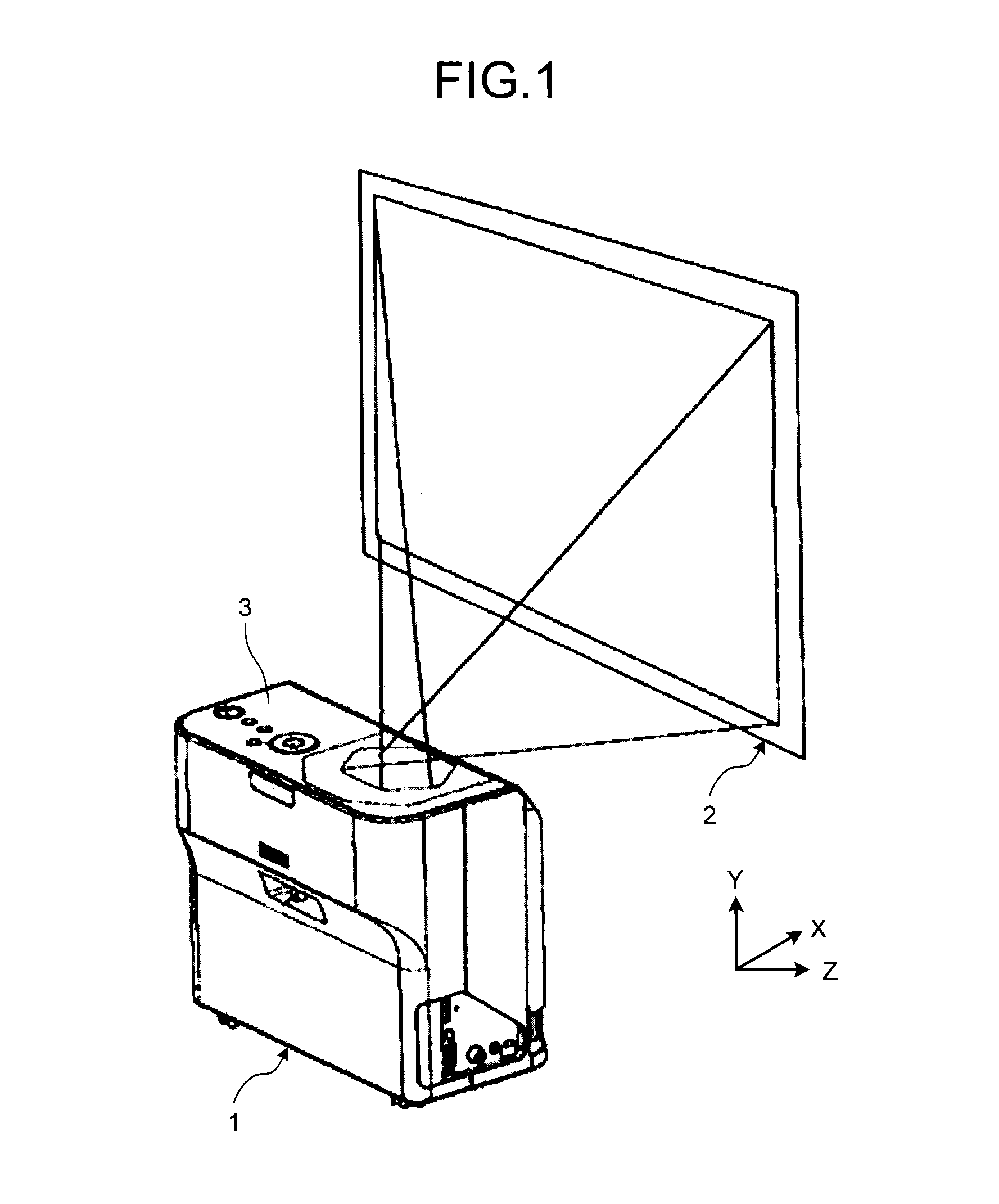
[0031]An explanation is given below of an embodiment of the present invention with reference to the drawings. FIG. 1 is an external perspective view that illustrates an image projection device 1 according to the present embodiment when viewed at an angle. The image projection device 1 generates a video on the basis of video data that is input from a personal computer, video camera, or the like, and projects and displays the video on a screen 2, or the like. As for liquid-crystal projectors, which are widely known as the image projection device 1, an improvement in the brightness, a reduction in costs, and the like, have been achieved in recent years due to a higher resolution of liquid crystal panels and a higher efficiency of light source lamps. Furthermore, small and lightweight image projection devices that use a digital micromirror device (DMD) have become popular, and the image projection devices have been widely used not only in offices and schools but also at homes. Particula...


PUM


Abstract

There are provided a button section; a contact-type switch that is provided in each of a plurality of directions; a button contact area that is provided on the back surface of the button section and that is brought into contact with the switch; a cover section that covers the periphery of the button section; and a flange section that is provided on the outer periphery of the button section and that is in contact with the cover section so as to restrict the button section from being ejected from inside a chassis, wherein the flange section includes cutouts at positions that are opposed to each other with the switch and the center position of the button section interposed therebetween.

Description

CROSS-REFERENCE TO RELATED APPLICATIONS[0001]The present application claims priority to and incorporates by reference the entire contents of Japanese Patent Application No. 2013-131181 filed in Japan on Jun. 21, 2013.BACKGROUND OF THE INVENTION[0002]1. Field of the Invention[0003]The present invention relates to a switch mechanism and an electronic device.[0004]2. Description of the Related Art[0005]There are conventional buttons that have button functions assigned to the left, right, top, and bottom of a single disk-shaped component in directions. There is an already-known method for, when an area near the boundary among the left, right, top, and bottom of the button is pressed, detecting the degree of operation and determining which button is to react by using the degree of operation. In Japanese Patent Application Laid-open No. 2012-141641, to prevent a wrong reaction of a button, when multiple buttons are operated, the degree of operation of each of the buttons is detected, and ...

Claims


Application Information

Patent Timeline
Patent Type & Authority Patents(United States)
IPC IPC(8): H01H3/12H01H13/14H01H25/04
CPCH01H25/041H01H2025/048
Inventor ISHIKAWA, NAOYUKIFUJIOKA, TETSUYAKANAI, HIDEOMIKAWA, AKIHISAYAMADA, MASAMICHIMIKUTSU, YASUNARITSUCHIYA, SATOSHI
Owner RICOH KK
Why Eureka
Try Eureka