Wear part for earth working equipment

Active Publication Date: 2017-11-09
ESCO GRP LLC
View PDF9 Cites 11 Cited by
  • Summary
  • Abstract
  • Description
  • Claims
  • Application Information

AI Technical Summary

Benefits of technology

[0005]The present invention pertains to wear parts for earth-working equipment, and in particular to a locking arrangement that is stron

Problems solved by technology

Wear members for earth-working equipment are commonl

Method used


Image

  • Wear part for earth working equipment
  • Wear part for earth working equipment
  • Wear part for earth working equipment

Examples


Example

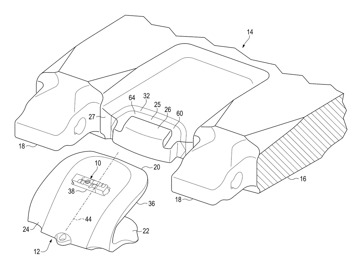
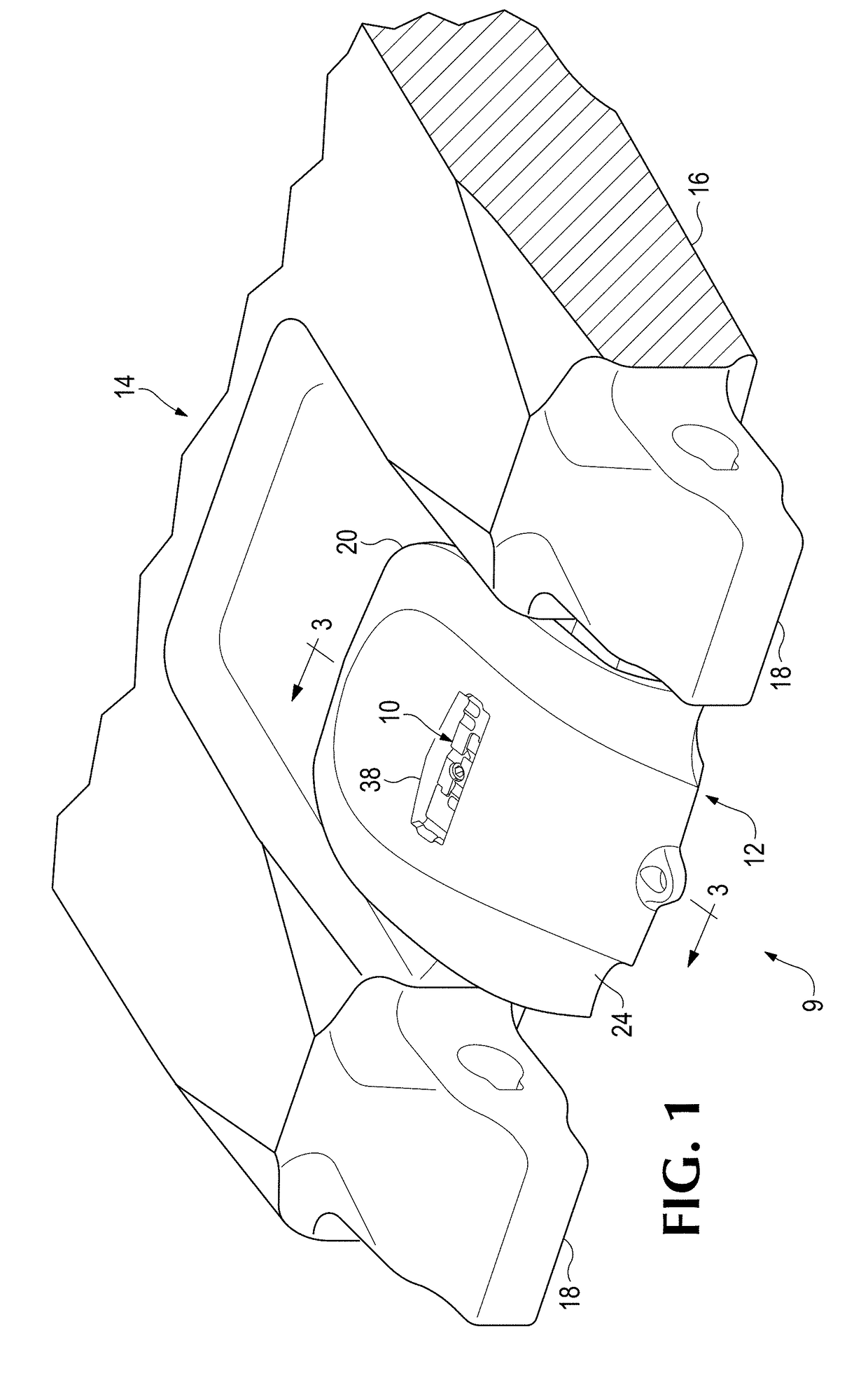
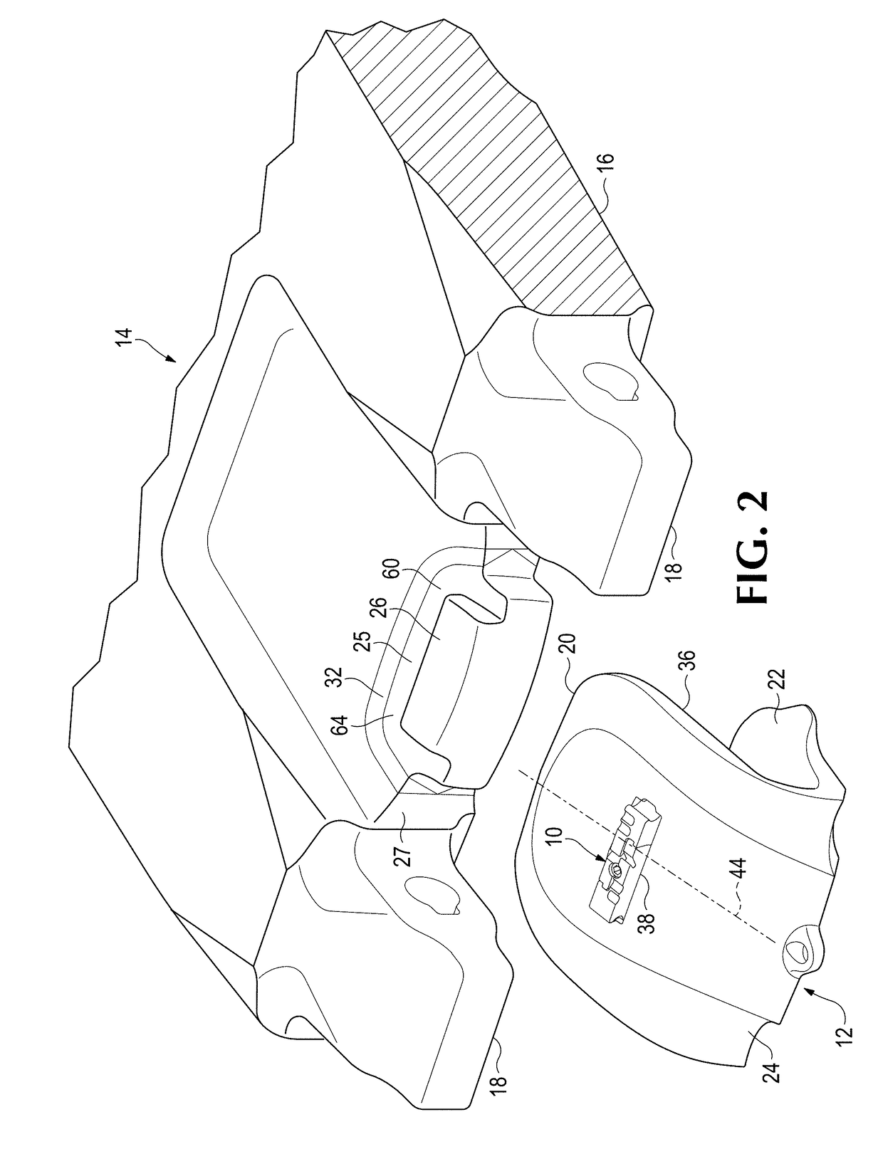
[0044]The present invention pertains to wear parts 9 for earth-working equipment 14. In one embodiment, wear part 9 includes a wear member 12 and a lock 10 for releasably securing the wear member 12 to earth-working equipment 14. In this example, wear member 12 is a shroud secured to a lip 16 of an excavating bucket by a lock 10 (FIGS. 1-22). Nevertheless, the wear members could have other forms (for example, other kinds of shrouds, excavating teeth, runners, liners, blades, etc.). Also the wear member could be secured to other kinds of earth-working equipment (e.g., mold boards, dredge cutter heads, ore chutes, truck bodies, etc.). In this description, relative terms such as forward, rearward, up or down are used for convenience of explanation with reference to the figure; other orientations are possible.

[0045]FIGS. 1-3 illustrate a shroud 12 fit onto a lip 16 between two noses 18 that support excavating points (not shown). In this one embodiment, lip 16 includes a base 25 that may...


PUM


Abstract

An articulated lock for securing a wear member to earth-working equipment includes a plurality of bodies interconnected for pivotal movement between an extended orientation with the bodies aligned and a retracted orientation with the bodies folded. The lock in the extended orientation can engage an opening of the wear member at an inner hold position to secure the wear member to the earth-working equipment or an outer release position. In the folded orientation the lock disengages from the opening of the wear member. Each body has a slot and a tab and, in the extended orientation, the tab of each body is received in the slot of the other body to limit separation of the bodies.

Description

RELATED APPLICATIONS[0001]This application claims priority to U.S. Provisional Patent Application No. 62 / 332,286, filed May 5, 2016, entitled “A Wear Part for Earth Working Equipment,” which is incorporated by reference in its entirety herein and made a part hereof.FIELD OF THE INVENTION[0002]The present invention pertains to wear members and locks for securing wear members to earth-working equipment.BACKGROUND OF THE INVENTION[0003]Wear parts are commonly attached to earth-working equipment such as excavating buckets and the like. For example, teeth and shrouds are generally mounted along the digging edge of an excavating bucket to protect the bucket from wear and to enhance the digging operation. Such wear assemblies typically include a base, a wear member, and a lock to releasably hold the wear member to the base. The base is fixed to the equipment as an integral part of the equipment, or as one or more components that are fixed to the equipment by welding or mechanical attachmen...

Claims


Application Information

Patent Timeline
IPC IPC(8): E02F9/28E02F3/40
CPCE02F9/2833E02F9/2808E02F3/40E02F9/2883E02F9/2841
Inventor ZENIER, SCOTT H.ROSKA, MICHAEL B.HANKLAND, JOEL S.
Owner ESCO GRP LLC
Why Eureka
Try Eureka