Lock for securing wear parts to earth-working equipment

a technology for earth-moving equipment and wear parts, applied in the direction of contact material, application, drags, etc., can solve the problems of wear parts for earth-moving equipment that are commonly subjected to harsh conditions and/or heavy loading, and achieve the effects of reducing costs, reducing ejection, and being easy to manufactur

Active Publication Date: 2009-05-26
ESCO GRP LLC
View PDF21 Cites 64 Cited by
  • Summary
  • Abstract
  • Description
  • Claims
  • Application Information

AI Technical Summary

Benefits of technology

[0004]The present invention pertains to improved locks for securing wear parts to earth-working equipment that are strong, durable, resistant to ejection, easy to manufacture at reduced costs, and simple and safe to use.
[0006]In accordance with one other aspect of the invention, the lock is hinged for movement between the retaining position and the release position. In the retaining position, the lock defines a robust pin that sets within an opening in the wear part to resist loads applied to the wear part during use. In the release position, the lock is articulated about the hinge to permit easy withdrawal or installation of the lock into or from the wear assembly, thus, permitting easy replacement of the wear part in the field.
[0008]In accordance with one other aspect of the invention, the lock is made of two bodies that are coupled together by a hinge, which preferably is formed of components that are integral to the bodies. This construction reduces the number of components, eases manufacturing, reduces costs, and strengthens the lock. In one preferred embodiment, one lock component is formed with an integral post while the other lock component has a complementary hole.
[0009]In accordance with another aspect of the invention, the lock is foldable for insertion into and release from a wear assembly, and includes a retainer to prevent folding while in the retaining position to prevent loss of the lock and wear part during use.
[0010]In accordance with another aspect of the invention, the lock includes a retainer that is threaded into a passage engaging both components. The retainer may have many different configurations. As examples only, the retainer may extend into both components, may be inserted along a seam between the components, and may extend in one of a multiple of directions. The retainer may also be a threaded rod, wedge or set screw, or have other configurations resisting pivoting or folding of the lock. The retainer is preferably easy to use, and enables installation and removal without the need for hammering, which leads to a safer and easier replacement process.

Problems solved by technology

Wear members for earth-working equipment are commonly subjected to harsh conditions and / or heavy loading.

Method used


Image

  • Lock for securing wear parts to earth-working equipment
  • Lock for securing wear parts to earth-working equipment
  • Lock for securing wear parts to earth-working equipment

Examples


Embodiment Construction

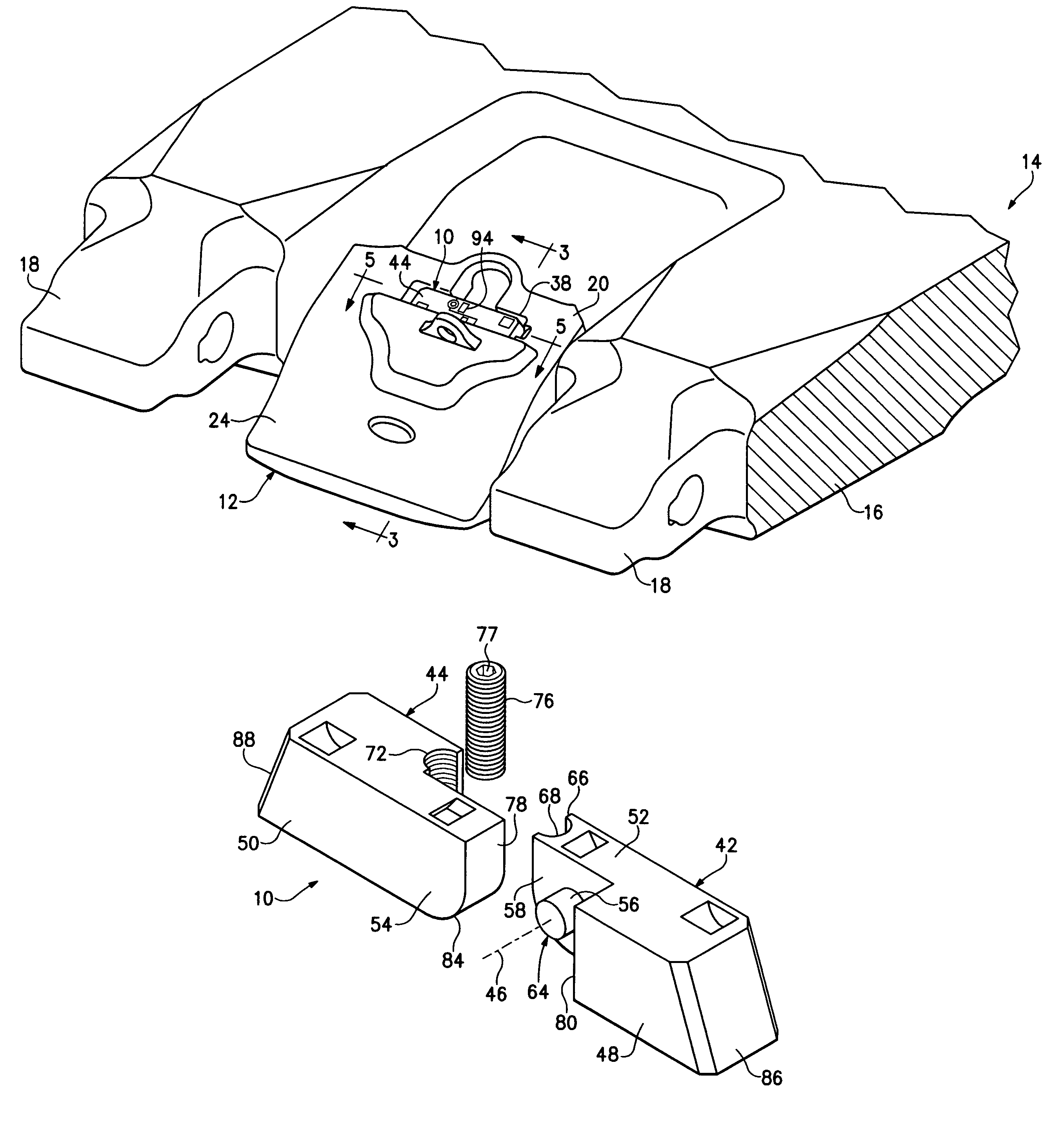
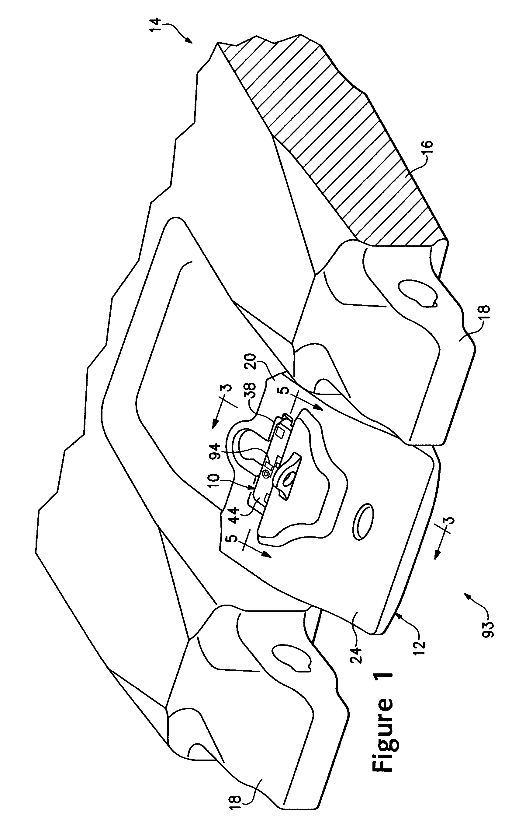
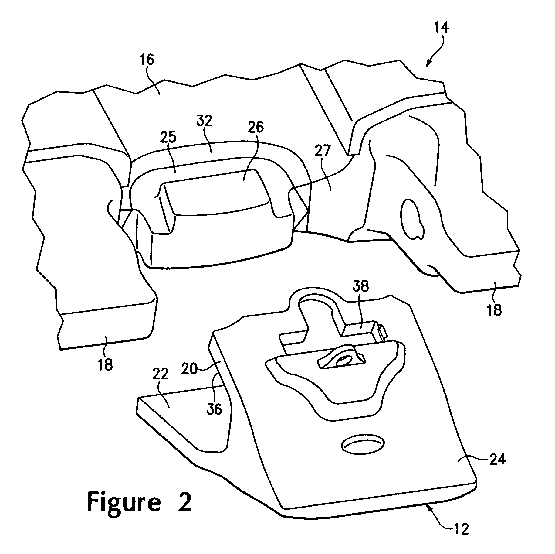
[0036]The present invention pertains to a lock 10 for releasably securing a wear member 12 to earth-working equipment 14. To illustrate the invention in this application, lock 10 is described in the context of securing a shroud to a lip of an excavating bucket. As an example, the disclosed shroud is generally as described in U.S. Patent Application Publication No. 2007-0044349, which is incorporated by reference. Nevertheless, a lock in accordance with the present invention could be used to secure other wear members including, for example, (i) other shrouds (e.g., as disclosed in U.S. Pat. No. 5,088,214, which is incorporated by reference), (ii) excavating teeth (e.g., as disclosed in U.S. Pat. No. 5,653,048, which is incorporated by reference), (iii) runners or other wear members for buckets (e.g., as disclosed in U.S. Pat. No. 5,241,765, which is incorporated herein by reference), (iv) wear members for other kinds of excavators such as dredge cutterheads (e.g., as disclosed in U.S...


PUM


Abstract

A lock for securing a wear part to earth-working equipment that is foldable between a retaining position to hold the wear part to the equipment and a release position that permits removal of the lock and release of the wear part from the equipment. The lock includes a retainer for releasably holding the lock in the retaining position. The retainer may comprise a threaded wedge received into a complementary threaded passage.

Description

FIELD OF THE INVENTION[0001]The present invention pertains to locks for securing wear parts to earth-working equipment.BACKGROUND OF THE INVENTION[0002]Wear parts are commonly attached to earth-working equipment such as excavating buckets and the like. For example, teeth and shrouds are generally mounted along the digging edge of an excavating bucket to protect the bucket from wear and to enhance the digging operation. Such wear assemblies typically include a base, a wear member, and a lock to releasably hold the wear member to the base. The base is fixed to the equipment as an integral part of the equipment, or as one or more components that are fixed to the equipment by welding or mechanical attachment. The wear member fits over the base. The assembled base and wear member cooperatively define an opening into which the lock is received to releasably hold the wear member to the base.[0003]Wear members for earth-working equipment are commonly subjected to harsh conditions and / or hea...

Claims


Application Information

Patent Timeline
Patent Type & Authority Patents(United States)
IPC IPC(8): E02F9/28A01B39/20
CPCE02F9/2833E02F3/36E02F9/28
Inventor MCCLANAHAN, ROBERT
Owner ESCO GRP LLC
Why Eureka
Try Eureka